EUREKA TOOL
Ostern 2022.
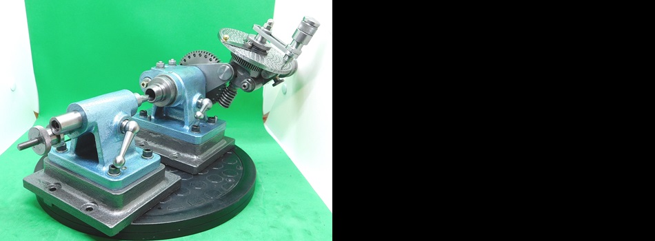
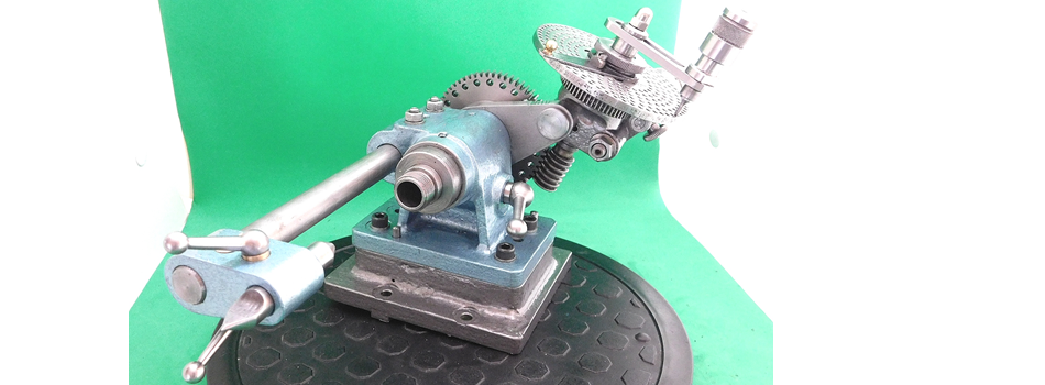
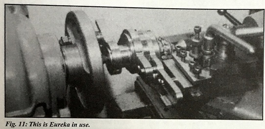
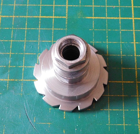
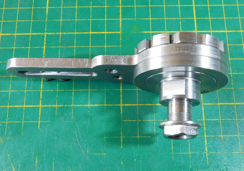
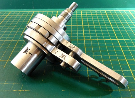
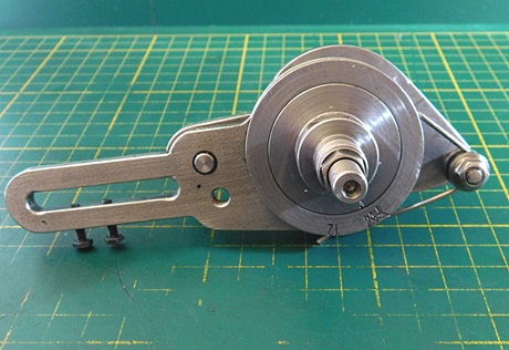
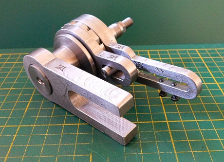
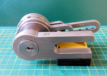
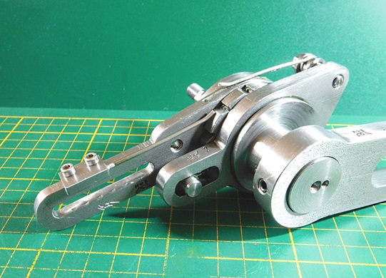
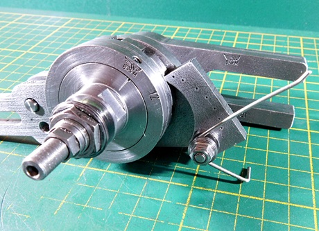
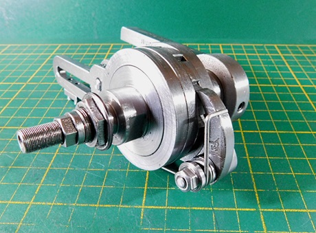
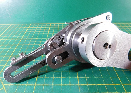
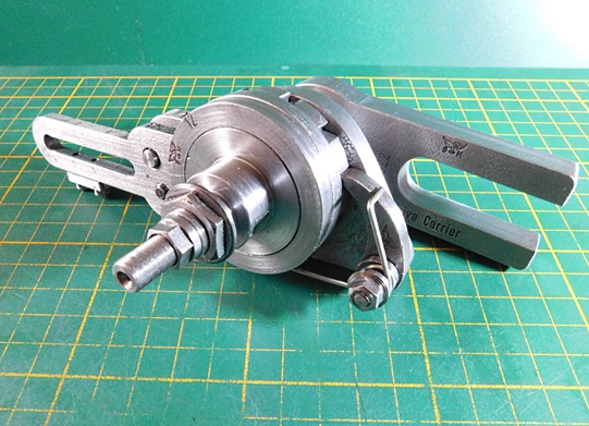
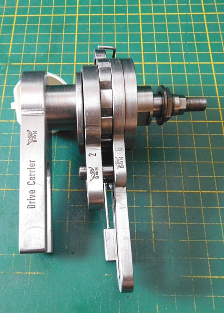
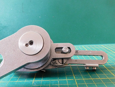
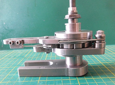
Durch die Beschäftigung mit selbst gebauten Abwälz-Fräsmaschinen für Zahnräder, bin ich auf ein Gerät gestoßen, mit dem es möglich ist, bei mehrschneidigen Formfräsern an jedem Zahn einen formgerechten Freiwinkel zu erzeugen.
Das Gerät bassier auf einem Patent aus den USA von Stephan M. Balzer. Pat.Nr. 535,127. vom März 1895 und einer Weiterentwicklung von Charles G. Taylor Pat.Nr. 817,885. vom April 1906.
Prof. D.H.Chaddock und Ivan Law haben die Idee aufgegriffen und in der Zeitschrift "Model Engeneer" in vereinfachter Form 1987 vorgestellt.
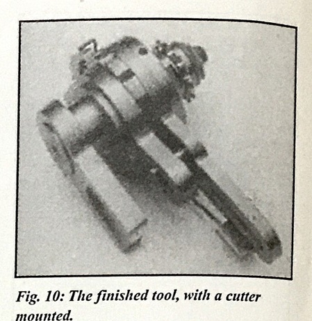
Die Zeichnungen fand ich in einer Heftenreihe aus England "Workshop Practice Series" Nr. 17. Die Zeichnungen und Maße sind in diesem Büchlein allerdings nicht gut zu erkennen.
Ich habe in einem Forum nachgefragt, ob jemand bessere Zeichnungen, evtl. noch aus der Zeitschrift "Model Engeneer" mir zur Verfügung stellen kann. Glücklicherweise bekam ich bessere Zeichnungen dafür.
Nun ging die Umrechnerei von Zoll zu Millimeter los. Zunächst auf zwei Stellen hinter dem Komma in Millimeter umgerechnet und dann an runde Maße angepasst. Die erhältlichen Materiealquerschnitte wurden natürlich auch mit einbezogen.
Nach dem alles erledigt war, konnte das Material bestellt und nach Lieferung los gelegt werden.
Die Materialkosten belaufen sich auf ca. 100,- €.
Stahl ist in der letzten Zeit exorbitant im Preis gestiegen.
While studying self-built gear hobbing machines, I came across a device with which it is possible to create a true-to-shape clearance angle on each tooth of multi-bladed form cutters.
The device is based on a patent from the USA by Stephan M. Balzer. Pat.No. 535,127. from March 1895 and a further development by Charles G. Taylor Pat.No. 817,885. from April 1906.
Prof. D.H.Chaddock and Ivan Law took up the idea and presented it in a simplified form in the magazine "Model Engeneer" in 1987.
I found the drawings in a booklet from England "Workshop Practice Series" No. 17, but the drawings and dimensions are not well visible in this booklet.
I asked in a forum if someone could provide me with better drawings, possibly still from the magazine "Model Engeneer". Fortunately I got better drawings for it.
Now the conversion from inch to millimeter started. First converted to millimeters to two decimal places and then adapted to round dimensions. The available material cross sections were of course also included.
After everything was done, the material could be ordered and started after delivery.
The material costs amount to approx. 100,- €.
The price of steel has risen exorbitantly in recent times.
Den kompletten metrischen Zeichnungssatz habe ich als PDF-Datei hinterlegt.
I have deposited the complete metric drawing set as a PDF file.
Die ersten Teile wurden gefertigt.
The first parts were manufactured.
19.04.2022
Ostern ist vorbei und es gab wieder Zeit Späne zu machen.
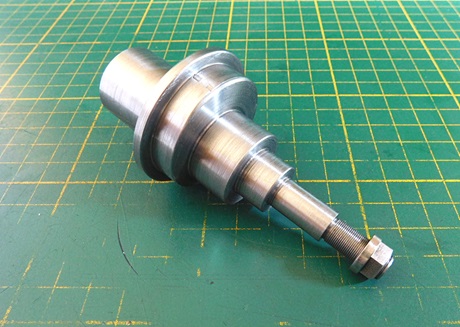
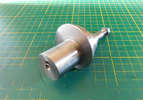
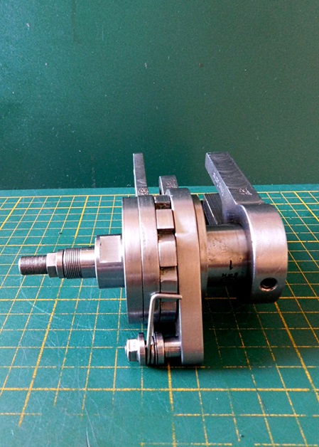
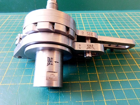
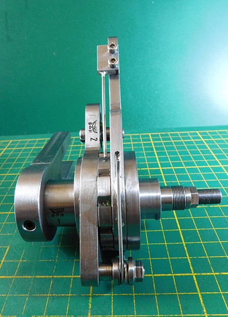
Heute war Part Nr. 1 dran. Die Welle mit ihren Zwei Excentern.
Material: 42 CrMo4.
Zur Anfertigung der Hauptwelle muss ich etwas erläutern. Die Welle herzustellen ist nicht ganz einfach, weil da insgesamt zwei Excenter vorhanden sind, die sich gegenseitig überlagern.
Zunächst habe ich die Welle auf das Maß Ø 45mm abgedreht, natürlich mit Reitstock-Unterstützung.
Danach in gleicher Aufspannung den Absatz für Part Nr.2 Ø 38mm angedreht.
Nun das Dreibackenfutter mit dem Ø 125 mm Vierbackenfutter mit einzel verstellbaren Backen gewechselt. Eine aufwändige Einstellerei mit der Messuhr für den Excenter, dessen Mittelpunkt 4,3mm (*besser 4,5mm) vom bisherigen Mittelpunkt liegt, begann.
Die Messuhr muss am Ende einen Vollausschlag von 8,6 mm (*besser 9 mm) zeigen. 90 Grad dazu muss der Ausschlag gleich sein.
Zur Kontrolle habe ich mir ein Distanzstück für die Backen gemacht. Auf dem Bett aufliegend und immer an der gleichen Stelle mit den Backen anschlagen. So bleibt die Winkligkeit erhalten.
Nun den Absatz Ø 25 mm , Ø 16 mm und die Welle Ø 10 mm in einer Aufspannung gedreht. Zuvor wurde eine neue Zentrierbohrung gesetzt und mit dem Rollkörner abgestützt.
Nach dem alles fertig war, wurde der Absatz für das M 8 x 0,5 mm Gewinde gedreht und an Part Nr. 7 angepasst. Wenn die M 8 x 0,5 mm Mutter fest gezogen ist, darf dieses Teil nicht klemmen und auch kein großes Spiel haben. Die Zentrierbohrung wurde im Anschluss mit sehr kleiner Zustellung fliegend weg gedreht um Platz zu schaffen für die Zentrierbohrung der entgültigen Rotationsachse.
Nun ging es an die Einstellung des zweiten Excenters. Dessen Mittelpunkt liegt 0,8 mm vom bisherigen Mittelpunkt und 90 Grad versetzt vom ersten Excenter entfernt. Bis ich das auf dem einzel verstellbaren Backenfutter hinbekommen hatte verging fast eine halbe Stunde. Nun konnte die Zentrierbohrung der entgültigen Rotationsachse gesetzt werden. Mit dem Rollkörner unterstützt wurde der Zapfen auf der Futterseite etwas Angedreht, bis die Welle rund war. Auf dieser Fläche konnte ich dann, nach dem Umspannen mit der Messuhr den Spannzapfen einstellen auf absoluten Rundlauf. Zentrieren und auf 25 mm abdrehen. Die Dreharbeiten an der Welle waren nun fertig.
Es muss nur noch eine Fläche für die Mitnehmerspannung angefräst werden.
*Durch das geänderte Maß ist die Schaltsicherheit besser gewährleistet. In der Zeichnung steht noch das ursprüngliche Maß.
Easter is over and there was time again to make chips.
Today was Part No. 1. The shaft with its two eccentrics.
Material: 42 Cr Mo 4.
I have to explain something about the production of the main shaft. Making the shaft is not easy, because there are two eccentrics in total, which overlap each other.
First I turned the shaft to the dimension Ø 45mm, of course with tailstock support.
Then I turned the shoulder for part no.2 Ø 38mm in the same clamping.
Now I changed the three-jaw chuck with the Ø 125 mm four-jaw rotary chuck with individuall adjustable jaws. An elaborate adjustment with the measuring clock for the Excenter, whose center is 4.3mm (*better 4,5 mm) from the previous center, began.
The dial gauge must show a full deflection of 8.6 mm (*better 9 mm) at the end. At 90 degrees, the deflection must be the same.
For control I made a distance piece for the jaws. Rest on the bed and always strike the jaws at the same point. So the angularity remains.
Now turned the heel Ø 25 mm , Ø 16 mm and the shaft Ø 10 mm in one clamping. Before this, a new centering hole was set and supported with the roller center punch.
After everything was ready, the shoulder for the M 8 x 0.5 mm thread was turned and adapted to Part No. 7. When the M 8 x 0.5 mm nut is tightened, this part should not jam or have much play. The centering hole was then turned away with a very small infeed to make room for the centering hole of the final rotation axis.
Now the second eccentric was set. Its center point is 0.8 mm from the previous center point and 90 degrees offset from the first eccentric. It took me almost half an hour to get this right on the single adjustable jaw chuck. Now the center hole of the final rotation axis could be set. Supported by the roller center punch, the journal on the chuck side was turned a little until the shaft was round. On this surface, I could then, after reclamping with the dial gauge, adjust the clamping spigot to absolute concentricity. Centering and turning to 25mm. The turning work on the shaft was now finished.
Only a surface for the driver tension must be milled.
*The changed dimension ensures better switching reliability. The drawing still shows the original measurement.
20.04.2022
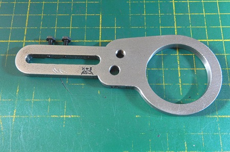
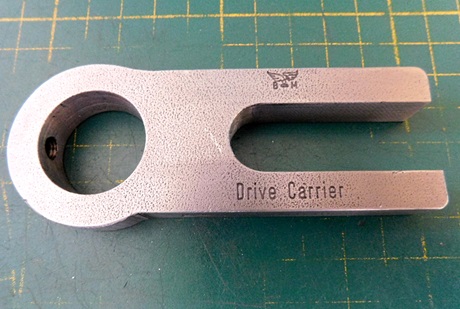
Heute habe ich den Mitnehmer zum Antrieb der Spindel zwischen den Spitzen gefertigt und die Spannfläche an der Welle für den Mitnehmer angefräst.
Material ist 12mm Flachstahl.
Eine Zeichnung dafür gab es nicht. Ich habe mich an den Bildern orientiert und eine Zeichnung dafür erstellt.
Today I made the driver to drive the spindle between the center and milled the clamping surface on the shaft for the driver.
Material is 12mm flat steel.
There was no drawing for it. I took my cue from the pictures and made a drawing for it.
Für die Wickelfeder habe ich zwei Anläufe benötigt. Bei der ersten Feder war die Wickelrichtung falsch. Da habe ich nicht aufgepasst.
Die zweite Feder war dann korrekt.
I needed two starts to wind the spring. With the first spring, the winding direction was wrong. I did not pay attention.
The second spring was then correct.
21.04.2022
Heute habe ich nur eine Kleinigkeit gefertigt.
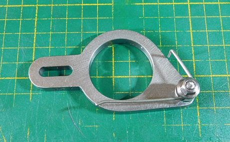
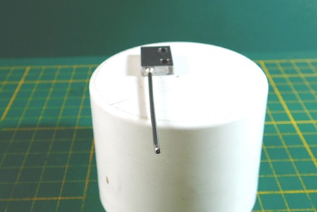
Den Federhalter mit eingelöteter Feder für eine der Sperrklinken.
Die Feder (Pianodraht) wurde mit Weichlotpaste in den Halter eingelötet.
Eine kleine Anmerkung zu dem Piano-Draht:
Es ist kein Draht der die Töne an einem Piano erzeugt, sondern ein Draht der für die Betätigung der Hammer verwendet wird.
Today I made only one small detail.
The spring holder with soldered spring for one of the ratchets.
The spring (piano wire) was soldered into the holder with soft solder paste.
A small note about the piano wire:
It is not a wire that produces the tones on a piano, but a wire that is used to operate the hammers.
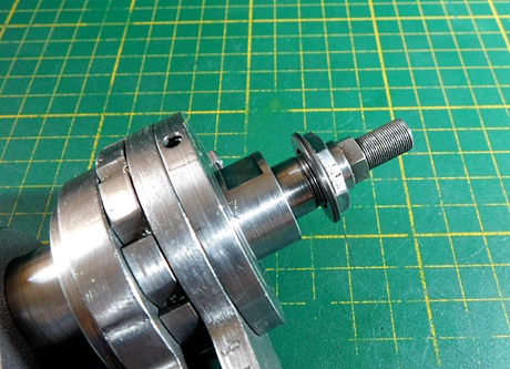
To prevent the winding spring from jumping off, it runs in a small recess.
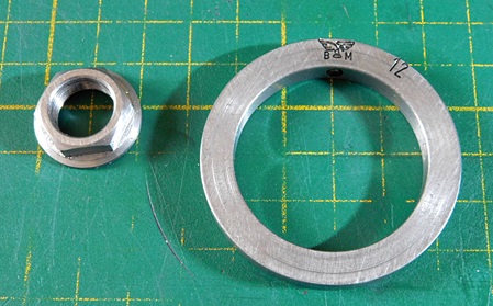
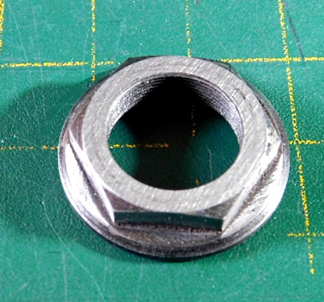
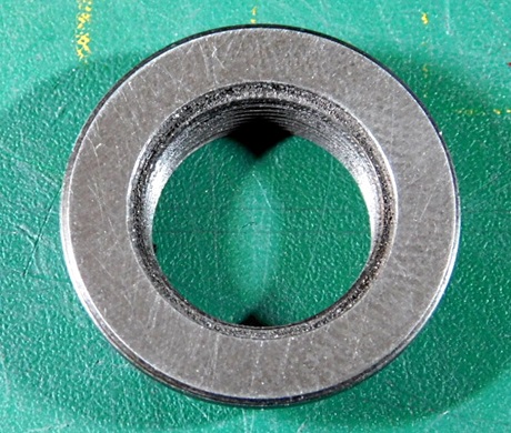
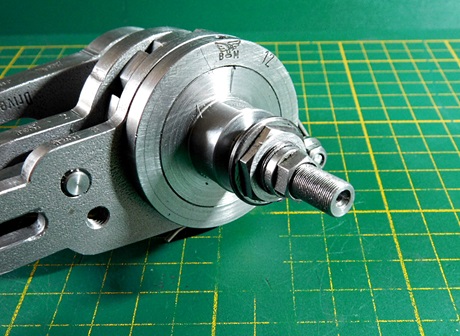
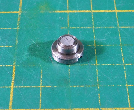
Die Befestigungsmutter für die späteren Fräser wurden aus 42 Cr Mo 4 gefertigt, gehärtet und angelassen. Das Gewinde ist ein M 13 x 0,5 mm Feingewinde.
The fastening nut for the later cutters were made of 42 Cr Mo 4, hardened and tempered. The threaded end is a M 13 x 0.5 mm fine thread.
25.04 2022
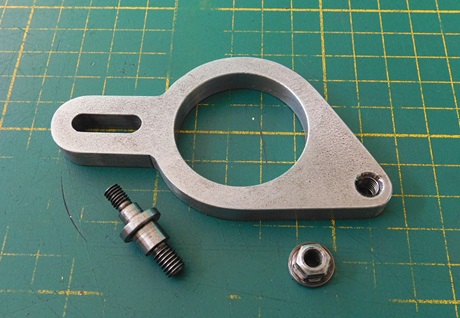
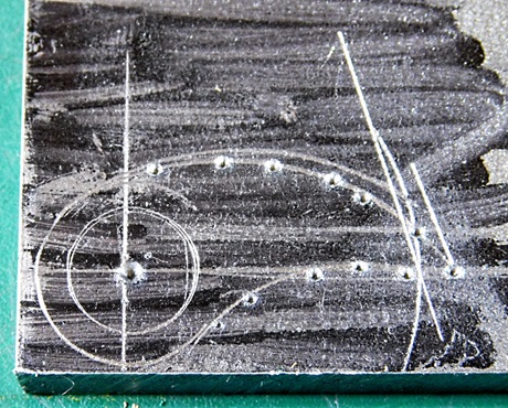
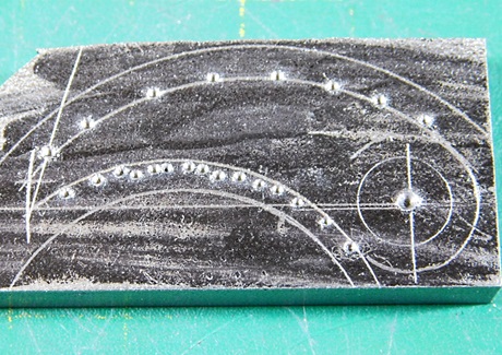
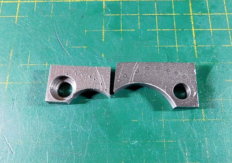
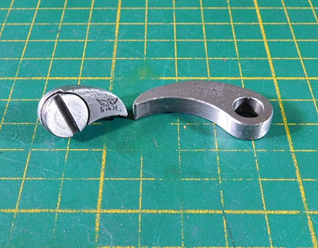
Die Sperrklinken habe ich zunächst auf 6mm Flachstahl angerissen, das Zentrum der Bohrung und die Kontour markiert.
Im Anschluss die Befestigungsbohrungen gefertigt und mit dem Schlagzahn den inneren Radius ausgefräst. Der Rest war Feil- und Schleifarbeit.
I first scribed the ratchets on 6mm flat steel, the center of the hole and the contour were marked.
Then I made the drill holes and milled out the inner radius with the fly cutter. The rest was filing and sanding work.
This happens when you harden 42 Cr Mo 4 and forget to temper it.
Die Sperrklinken müssen noch Einsatz gehärtet werden. Dann ist das Gerät fertig zum Gebrauch.
The ratchets still have to be case-hardened. Then the device is ready for use.
26.04.2022
Die Sperrklinken sind nun auch gehärtet. Normalerweise lässt sich Baustahl (S 235 JR) nicht härten.
Ich bin folgendermaßen vor gegangen. Zunächst die Klinken auf Kirsch-Rotglut erwärmt und in Stickstoff-Härtepulver abkühlen lassen.
Im Anschluss nochmals erwärmt und in Wasser abgeschreckt. Die Feilprobe ergab, dass die Oberfläche sehr hart war. Die Feile konnte nichts abnehemen.
Die Klinken wurden nicht angelassen, da sie im Kern nicht hart sind.
Die Halteschrauben der Klinken bestehen aus 42 Cr Mo 4 Stahl und wurden ebenfals gehärtet und im Anschluss angelassen. Das Anlassen ist sehr wichtig, sonst sind die Teile zu Hart und brechen bei der geringsten Belastung.
Nachdem wurden alle Teile gesäubert, entfettet und die Schrauben mit Loctite 243 eingesetzt.
Die beweglichen Teile wurden im Anschluss geölt.
The locking levers are now also hardened. Normally mild steel (S 235 JR) cannot be hardened.
I proceeded as follows. First heat the lock levers to cherry red colour and let cool in the nitrogen curing powder.
Then heated again and quenched in water. The sample with a file showed that the surface was very hard. The file couldn’t remove the material.
The bushings were not left on because they are not hard at the core.
The clamping screws of the bushings are made of 42 Cr Mo 4 steel and have been hardened and then tempered. Tempering is very important, otherwise the parts are too hard and break at the least load.
All parts were then cleaned, degreased and the screws were screwed in with Loctite 243.
The moving parts were then oiled.
With new made screw tempered after hardening.
Resümee:
Das Teil zu fertigen war eine schöne Herausforderung und eine anspruchsvolle Arbeit. Einiges Kopfzerbrechen gab es bei der Anfertigung der Hauptwelle mit ihren zwei, sich überlagerten, Excentern. Die Einstellerei mit dem einzel verstellbaren Vierbackenfutter dauerte gefühlt Stunden. Es war das erste mal, dass ich mit dem Stahl 42 Cr Mo 4 gearbeitet habe. Die Bearbeitbarkeit auf der Dreh-und Fräsmaschine war gut. Ich habe gelernt, dass man das Material, nach dem Härten, unbedingt anlassen muss.
Der Pianodraht ließ sich gut verarbeiten.
Ich habe das Erste mal normalen Baustahl mit dem Sickstoff- Härtepulver behandelt und das Ergebnis war hervorragend.
Jetzt muss ich nur noch mal ausprobieren, wie sich das Teil bei der Herstellung von Formfräsern verhält.
Resume:
Making the part was a nice challenge and a demanding job. There was some headache in the production of the main shaft with its two overlapping eccentrics. Adjusting the single adjustable four-jaw chuck took what felt like hours. It was the first time I had worked with the 42 Cr Mo 4 steel. Machinability on the lathe and milling machine was good. I learned that it is important to temper the material after hardening.
The piano wire was easy to work with.
The first time I treated mild steel with the nitrogen hardening powder, the result was excellent.
Now I just have to try out how the part behaves in the production of form cutters.
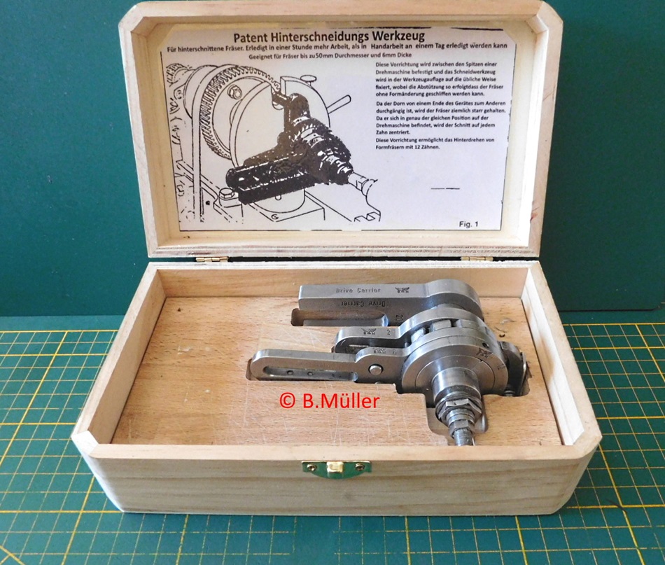
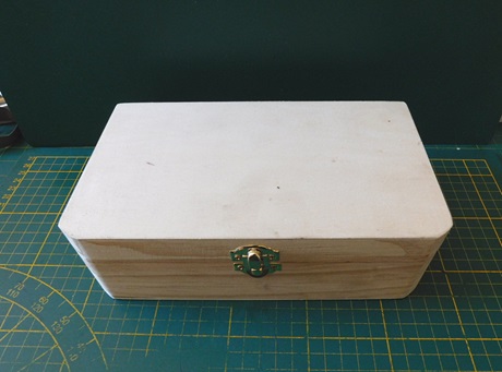
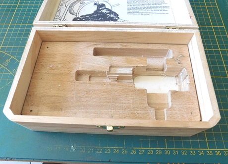
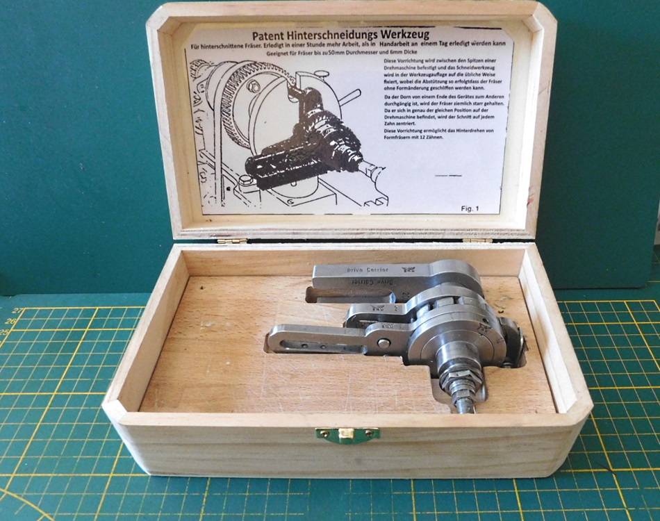
Zu guter letzt, hat das Gerät noch eine Aufbewahrungsbox erhalten.
Ein Holzschatulle aus einem 1€-Laden wurde etwas modifiziert.
Dazu wurde aus einem Reststück Buchenholz ein Formeinsatz gefräst und mit dem Schatullenboden verschraubt.
Last but not least, the unit has been given a storage box.
A wooden box from a 1€ shop was slightly modified.
For this purpose, a moulded insert was milled from a leftover piece of beech wood and screwed to the bottom of the casket.
