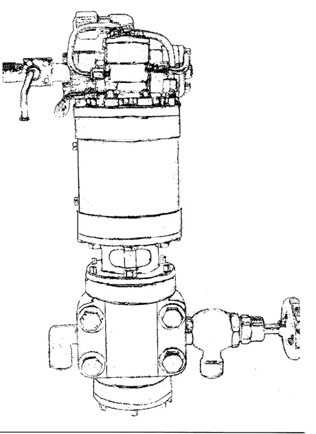
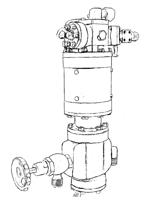
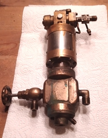
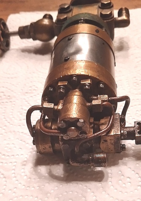
Dampfprojekte
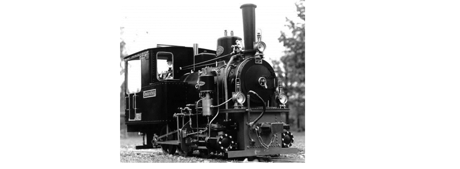
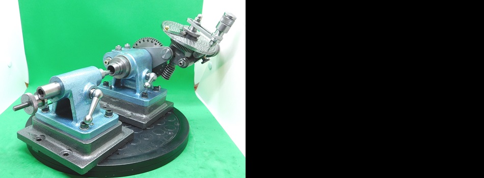
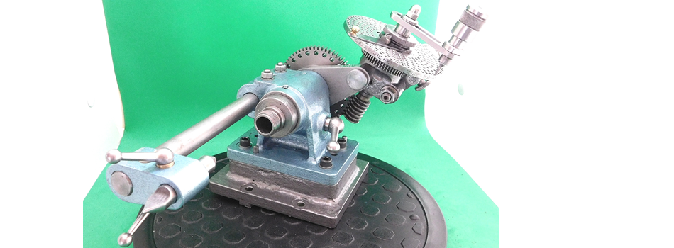
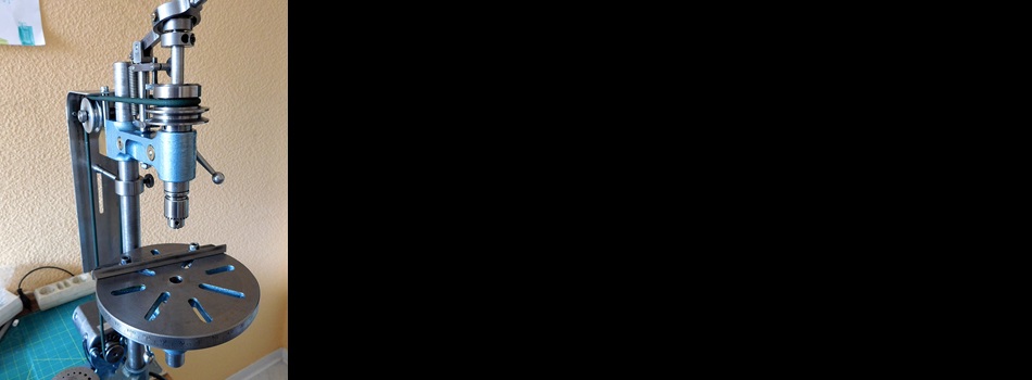
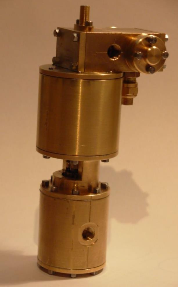
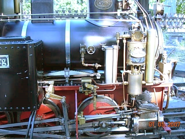
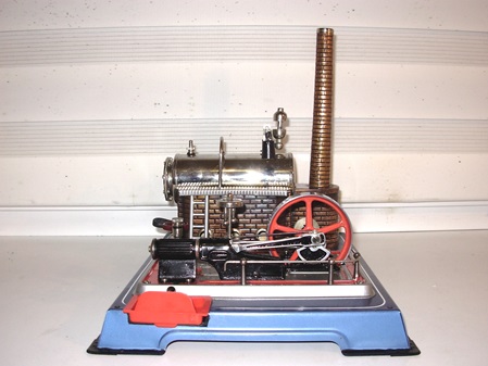
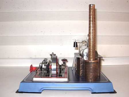
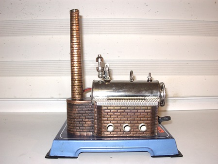
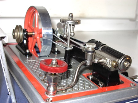
Hier sehen sie einige Dampfmaschinen, die ich in Arbeit hatte oder habe.
Here you can see some steam engines that I had or have in work.
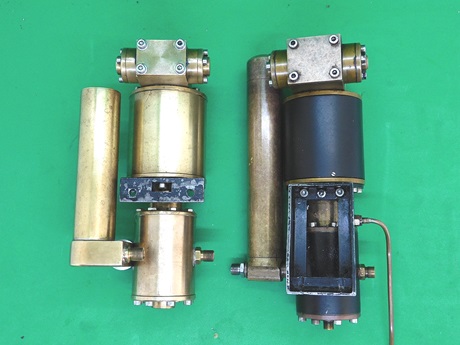
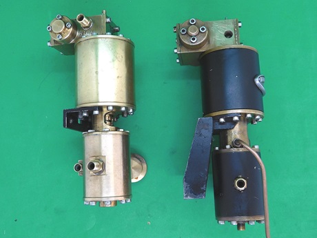
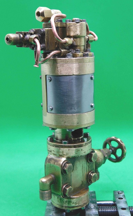
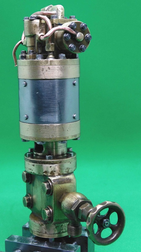
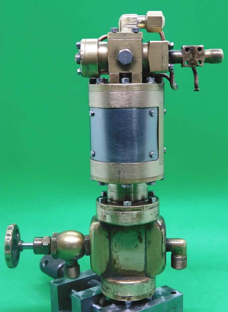
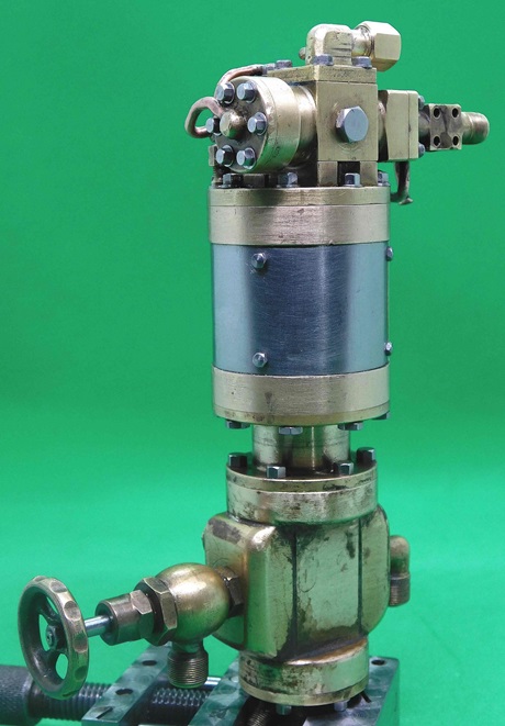
Revision zweier Dampfpumpenkurzen
Overhaul of two steam pumps
28.09.2024
Zu früh gefreut!!
Die Pumpe läuft zwar, fördert aber kein Wasser.
Beim Dampffest des DBC-Rhein-Main e.V. in diesem Jahr, hatte der Eigner der Pumpe, seine Lok mit dabei. Ich habe die Pumpe nochmals zerlegt, dabei aber keine Unregelmäßigkeiten feststellen können. Beim Zerlegen sind mir 3 der vier Ventilkugeln in's Gras gefallen und waren verschwunden. Am Nächsten Tag hatte ich mein Sortiment an Ventilkugeln mit gebracht und neu Kugeln eingesetzt. Das Pumpengehäuse neu abgedichtet und mit Pressluft geprüft. Die Pumpe läuft und baut Druck auf.
Im Anschluss die Pumpe an die Lokomotive gebaut und angeschlossen. Erste Probe -- Die Pumpe läuft, fördert aber kein Wasser. Nach eingehender Untersuchung der Anschlussleitungen habe ich dann festgestellt, dass der Lötnippel an der Saugseite undicht war. Der Nippel war nicht richtig Dicht verlötet und hat an dieser Stelle Luft gezogen. So konnte die Pumpe kein Wasser fördern.
Einen neuen Nippel hatte ich noch dabei. Aller zunächst mal gesäubert und den Nippel mit einem kurzen Stück Silikonschlauch mit der Wasser-Zuleitung verbunden.
Die Pumpe fördert Wasser.
Rejoiced too soon!
The pump is running, but not pumping water.
At the DBC-Rhein-Main e.V. steam festival this year, the owner of the pump had his locomotive with him. I disassembled the pump again, but found no irregularities. When I was disassembling it, 3 of the four valve balls fell into the grass and were missing. The next day I brought my assortment of valve balls with me and fitted new balls. The pump housing was resealed and tested with compressed air.
The pump is running and building up pressure.
I then fitted the pump to the locomotive and connected it up. First test -- The pump runs, but does not pump any water. After a thorough examination of the connection pipes, I realised that the soldering nipple on the suction side was leaking. The nipple was not soldered properly and was drawing air at this point. This meant that the pump could not pump any water.
I still had a new nipple with me. I cleaned everything first and connected the nipple to the water inlet pipe with a short piece of silicone tube.
The pump delivers water.
25.09.2023
Teil 1
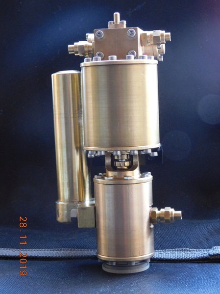
Nach vier Jahren hat der Eigner einer meiner Dampfpumpen Probleme mit seiner Pumpe. Angeblich fördert sie kein Wasser in den Kessel.
Er hat die Pumpe mir übergeben, mit der Bitte mal nach zu schauen was das Problem sei.
Die Pumpe hat nach seinen Angaben im Winter einmal Frost abbekommen. Das ist gar nicht gut für so ein kleines Wunderwerk.
Ich habe die Pumpe total zerlegt und gereinigt. Mir fiel auf, dass die Schleppschieber-Stange krumm war und im Steuerblock klemmte. Ich habe die Stange erneuert und die Bohrung dann nach gerieben , damit sie wieder frei laufen konnte.
Die Pumpe wurde neu abgedichtet und die verschlissene Stopfbuchspackung an der Dampfseite erneuert.
Der Steuerschieber wurde neu eingestellt und dann war der Probelauf, zunächst ohne Pumpen-Unterteil fällig.
Die Pumpe schnurrte los, als gäbe es kein halten mehr.
Nachdem der Pumpenkörper wieder angeschraubt war, konnte der Probelauf mit Pumpenteil statt finden. Alles verlief nach meiner Zufriedenheit. Als nächstes sollte die Pumpe auch fördern.
Also das Gerät in einen Topf mit Wasser gestellt und die Pumpe mit Druck beaufschlagt. Was soll ich sagen sie Fördert und baut Druck auf.
Alles wieder in Ordnung.
Teil 2
Die Nächste Arbeit war die Revision der Pumpe an unserer Vereins-Lok. Diese Pumpe ist seit über 25 Jahren eine Dauerleihgabe meinerseits an den Verein.
In den letzten Jahren haben da mehrere, teils erfahrene, aber auch unerfahrene Zeitgenossen daran versucht auftretende Probleme zu beseitigen. So schaut die Pumpe auch nach Jahren des Gebrauches aus.
Einige Anschlüsse sind verbogen und müssen erneuert werden. Das Öl-Rückschlag-Ventil war undicht geworden und dadurch drückte es Dampf in den mechanischen Öler der Pumpe.
Die Pumpe startete nur sehr wiederwillig.
Nach der Demontage stellt ich fest, dass sich der Schleuder-Schieber auseinander gedreht hatte. Das Problem ist mir bekannt. Die Verschraubung habe ich erneut mit Schraubensicherung wieder zusammen gebaut.
Nachdem alles wieder eingedichtet und Verschraubt war, konnte der Probelauf starten. Wie erwartet lief die Pumpe zu meiner vollen Zufriedenheit.
Die Neuen Anschlüsse für die Dampfzufuhr und das Rückschlag-Ventil für die Ölversorgung muss ich noch anfertigen.
Ich denke, am letzten Fahrtag des Vereines, im Oktober können beide Pumpen wieder eingesetzt werden.
Part 1
After four years, the owner of one of my steam pumps has problems with his pump. He says it is not pumping water into the boiler.
He handed the pump over to me and asked me to check what the problem was.
According to him, the pump has been exposed to frost once during the winter. That's not good for such a small wonder.
I totally disassembled and cleaned the pump. I found that the slider rod was crooked and stuck in the control block. I replaced the rod and then reamed the bore so that it could run freely again.
The pump was resealed and the worn gland packing on the steam side was replaced.
The control valve was readjusted and then the test run was due, initially without the pump lower part.
The pump purred away as if there was no stopping it.
After the pump body was screwed back on, the test run with the pump part could take place. Everything went according to my satisfaction. Next, the pump should also deliver.
So I put the device in a pot of water and pressurised the pump. What can I say? It delivers and builds up pressure.
Everything is fine again.
Part 2
The next job was the revision of the pump on our club locomotive. This pump has been on permanent loan to the club for over 25 years.
In the last few years, several, partly experienced, but also inexperienced contemporaries have tried to eliminate problems that have arisen. This is how the pump looks even after years of noise.
Some connections are bent and need to be replaced. The oil check valve had become leaky, forcing steam into the pump's mechanical lubricator.
The pump started only very reluctantly.
After disassembly, I noticed that the slingshot slide had come apart. I was aware of the problem. I reassembled the screw connection with threadlocker.
After everything was resealed and screwed together, the test run could start. As expected, the pump ran to my complete satisfaction.
I still have to make the new connections for the steam supply and the non-return valve for the oil supply.
I think that both pumps can be used again on the last driving day of the association in October.
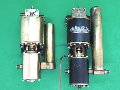
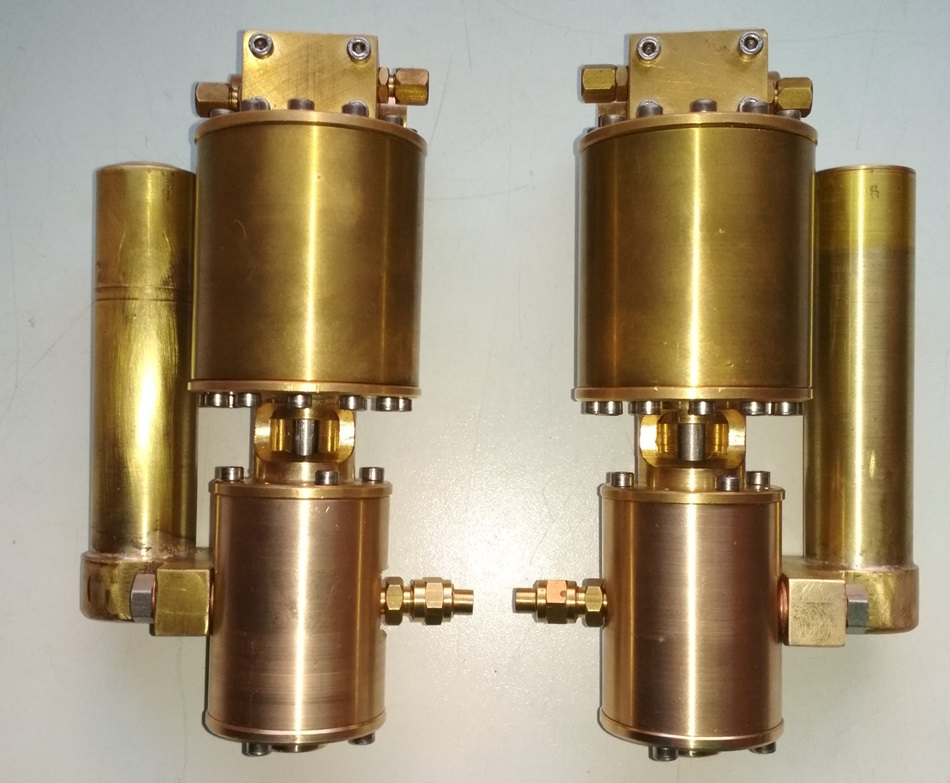
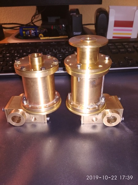
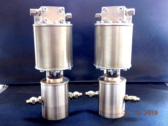
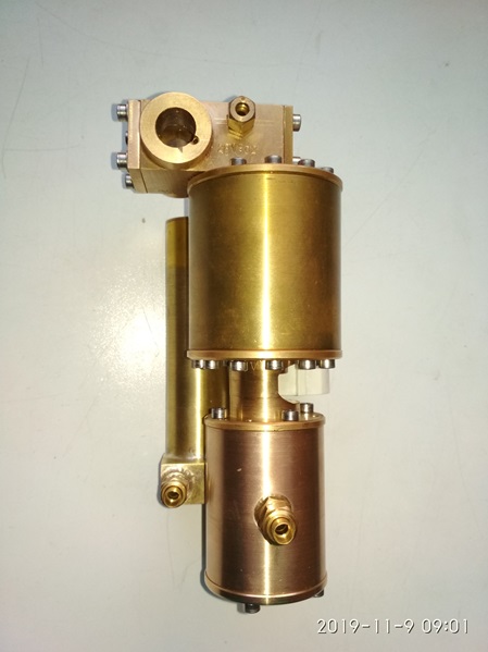
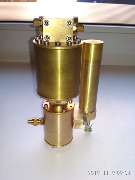
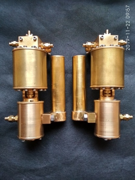
On the left, the owner's pump.
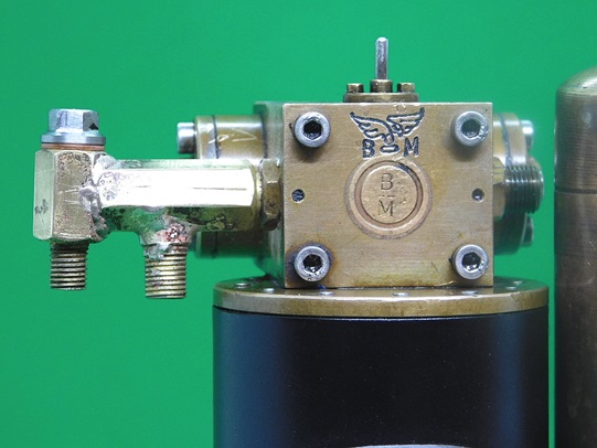
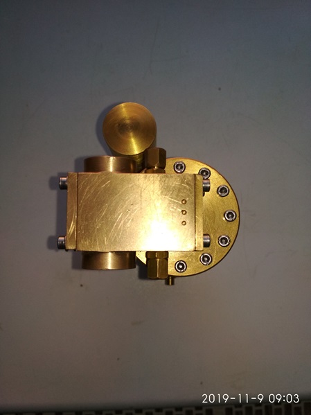
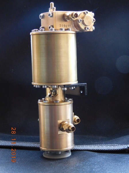
He asked me to engrave my logo on the pump.
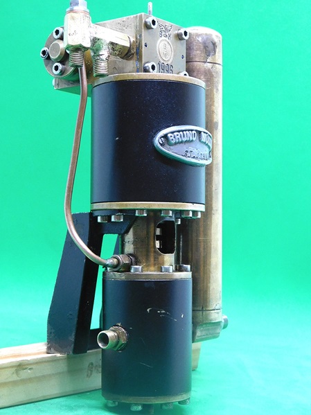
I also engraved my logo on the pump of the club locomotive (right).
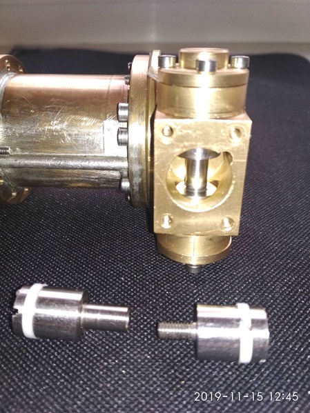
New fitting block for the pump of the club locomotive.
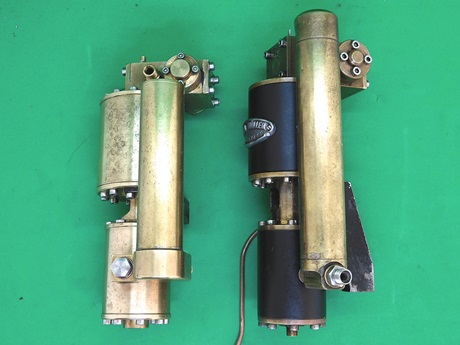
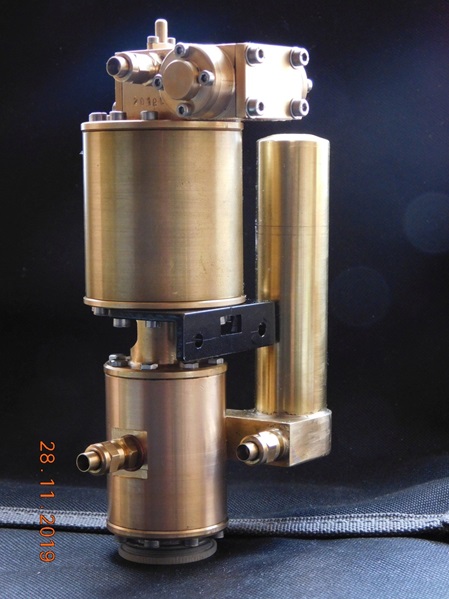
Die Rohrleitung zwischen den Zylindern bei der Vereins-Pumpe ist für das Ableiten von Schlabberwasser der Stopfbuchsen.
The pipe between the cylinders on the club pump is for draining off slop water from the stuffing boxes.
Revision einer Dampf-Speisepumpe mit Knorr P-Steuerung.
Revision of a steam feed pump with Knorr P valve control.
09.02.2023
Ich habe von einem Vereinskameraden eine Pumpe zur Revision bekommen.
Wer die Pumpe jemals gebaut hatte ist mir unbekannt.
Die Pumpe wollte nicht mehr laufen. Die Pumpe hat eine P-Steuerung, wie sie die Fa. Knorr bei ihren originalen Luftpumpen verwendet hatte.
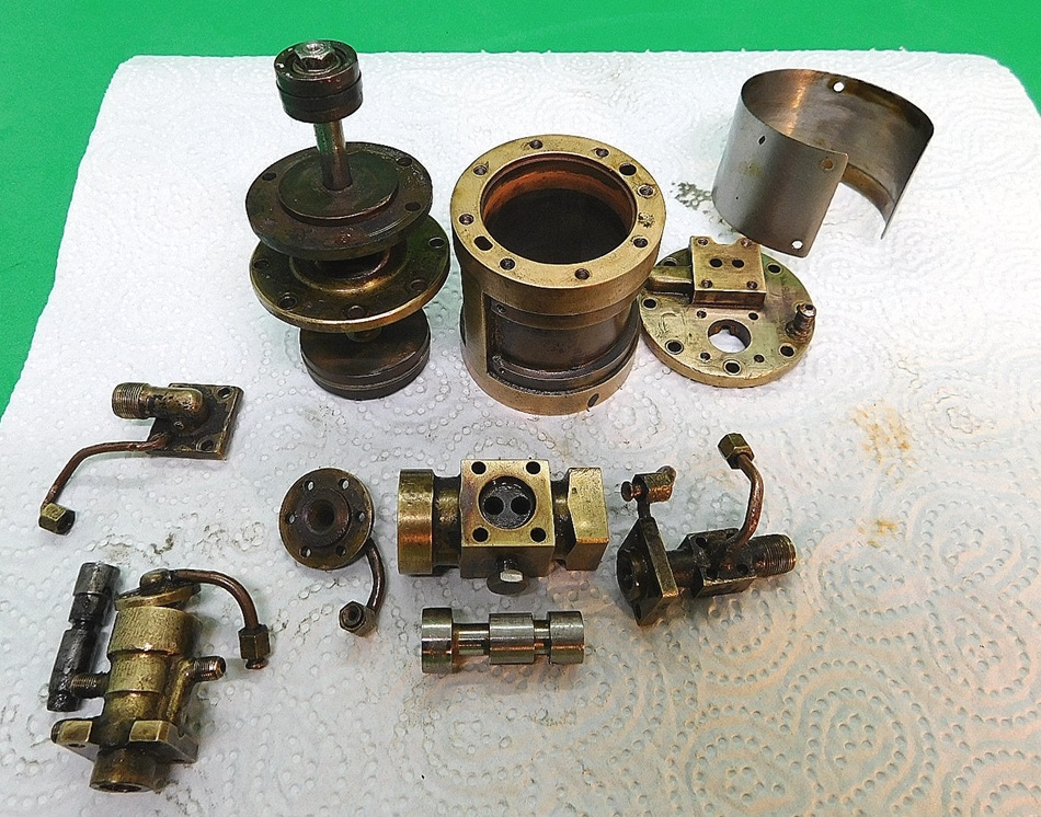
Ich habe zunächst die Pumpe total zerlegt und soweit möglich gereinigt. Der Übeltäter war auch schnell gefunden. Der Hilfsschieber der P-Steuerung war total vergammelt und teilweise korrodiert. Diesen musste ich neu anfertigen.
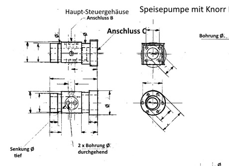
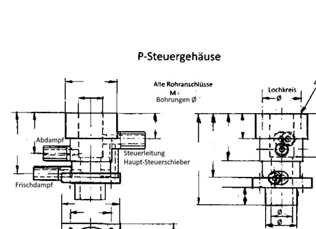
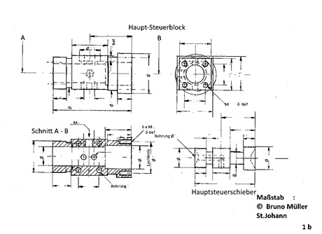
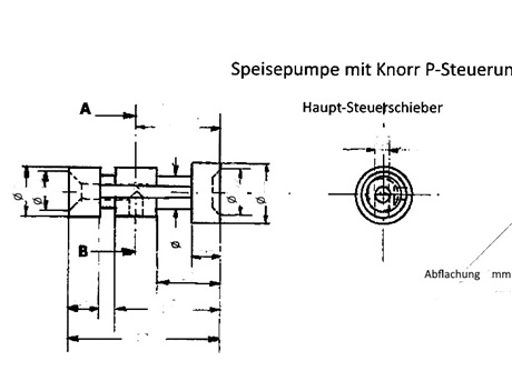
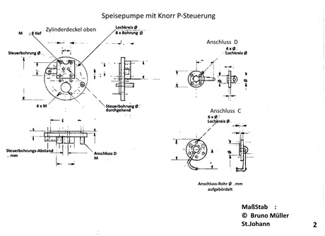
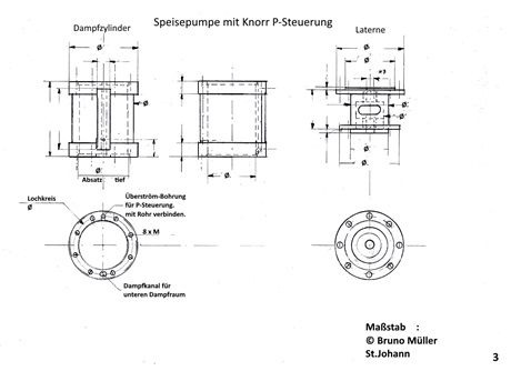
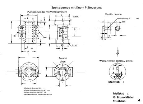
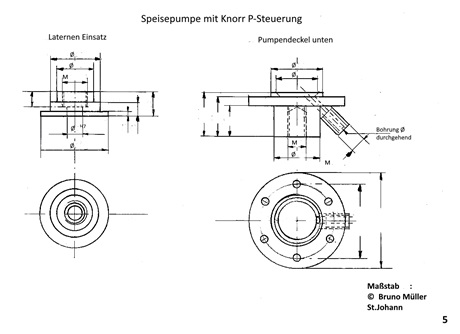
Bei dieser Gelegenheit habe ich die komplette Pumpe vermessen und Zeichnungen dafür angefertigt. Durch die Vermessung der Pumpe und die Anfertigung der Zeichnungen, habe ich erst die Funktion dieser Pumpe verstanden.
Der Erbauer der Pumpe hatte wohl einige Zoll-Werkzeuge zur Verfügung, anders sind die sehr krummen Maße der Steuerkolben nicht zu erklären. Die Schraubverbindungen für die einzelnen Komponenten gehen von M 2 über M 2,2 und M 2,5 bis M 3.
Anschluss für Zudampf und Abdampf wurden mit M 7,5 x ?? realisiert. Ein sehr ungewöhnliches Gewinde. Kann natürlich ein exotisches Zollgewinde sein.
Bei einer evtl. Nachfertigung werde ich natürlich gängigere Gewinde vorsehen.
Zunächst einige Bilder der Pumpe, so wie ich sie bekam.
I have received a pump from a club member for revision.
Who had ever built the pump is unknown to me.
The pump did not want to run anymore. The pump has a P-control, as the company Knorr had used in their original air pumps.
I first totally disassembled the pump and cleaned it as much as possible. The culprit was also quickly found. The auxiliary slide of the P-control was totally rotten and partially corroded. I had to make a new one.
On this occasion I measured the complete pump and made drawings for it. Only by measuring the pump and making the drawings, I understood the function of this pump.
The builder of the pump probably had some inch tools at his disposal, otherwise the very crooked dimensions of the control pistons cannot be explained. The screw connections for the individual components go from M 2 over M 2.2 and M 2.5 to M 3.
The connection for supply and exhaust steam was realised with M 7.5 x ?? A very unusual thread. Could of course be an exotic inch thread.
In case of a possible reproduction, I will of course provide more common threads.
First some pictures of the pump as I got it.
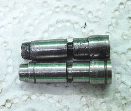
Den P-Schieber habe ich neu angefertigt. Ich habe Öl-Nuten eingestochen um beim Betrieb eine bessere Abdichtung zu erhalten. Bei der Demontage ist mir eine Entlüftungsleitung für den Haupf-Steuerschieber abgebrochen.Diese musste ich neu anfertigen.
Bei dem Versuch diese Leitung in den Abdampf-Anschluss zu löten, ist der Abdampf-Anschluss teilweise angeschmolzen. Es war wohl ein Gussteil aus Einem Material zum Wachs-Ausschmelz-Verfahren, mit niedrigem Schmelzpunkt. Ich habe dieses Teil aus Messing neu angefertigt. Den Abdampfanschluss habe ich dann mit einem Gewinde M 8 x 0,5 versehen. Zur Montage der Abdampfleitung habe ich gleich eine entsprechende Überwurfmutter gefertigt.
Fast alle Verbindungsschrauben mußten ersetzt werden. Die Schraubenköpfe waren ganz gewaltig vergammelt.
Einige Schrauben waren abgerissen und mussten aufwändig ausgebohrt werden.
Ich habe diese Schrauben durch Edelstahlschrauben ersetzt.
I made a new P-slide. I cut oil grooves in order to obtain a better seal during operation. During disassembly, a vent pipe for the main control valve broke off.
I had to make a new one. When I tried to solder this pipe into the exhaust steam connection, the exhaust steam connection partially melted. It was probably a casting made of a material for the wax melting-out process, with a low melting point. I made this part from brass. I then fitted the exhaust steam connection with an M 8 x 0.5 thread. To mount the exhaust pipe, I immediately made a corresponding union nut.
Almost all the connecting screws had to be replaced. The heads of the screws were badly rotten.
Some of the screws were torn off and had to be drilled out at great expense.
I replaced these screws with stainless steel screws.
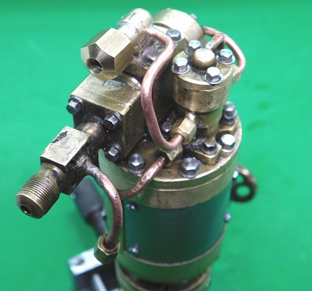
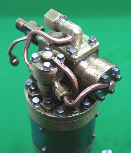
Einige Bilder der revidierten Pumpe.
Some pictures of the revised pump.
Old, rotten P-valve and newly made P-valve with oil grooves.
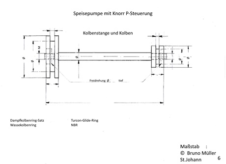
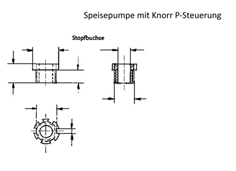
Den Zeichnungssatz habe ich nun fertig gestellt. Teilweise in einem anderen Maßstab, damit man die Einzelheiten besser erkennen kann.
Die Bilder der Zeichnungen habe ich hier eingestellt, allerdings ohne Maße. Die Bemaßung ist meine geistige Arbeit.
I have now finished the set of drawings. Partly in a different scale, so that you can see the details better.
I have put the pictures of the drawings here, but without dimensions. The dimensioning is my brainwork.
30.11.2019
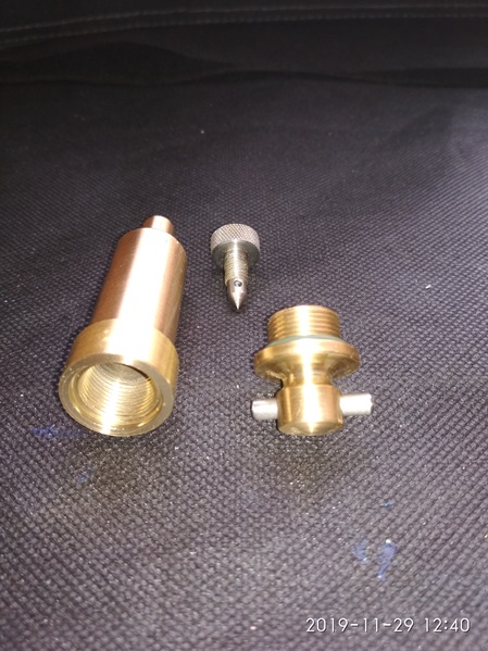
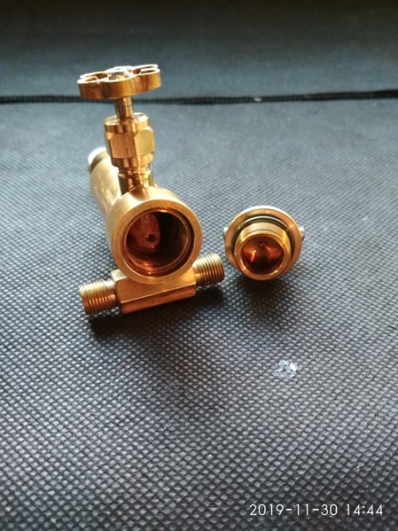
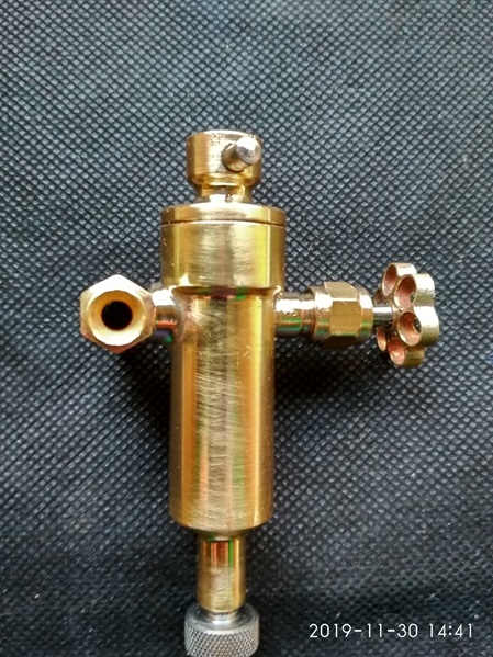
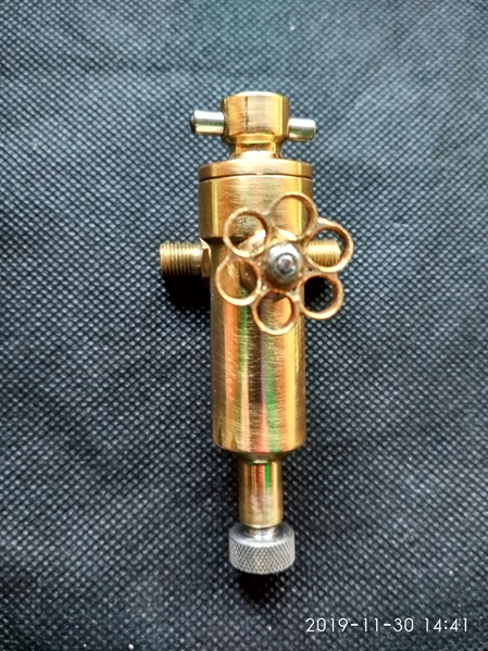
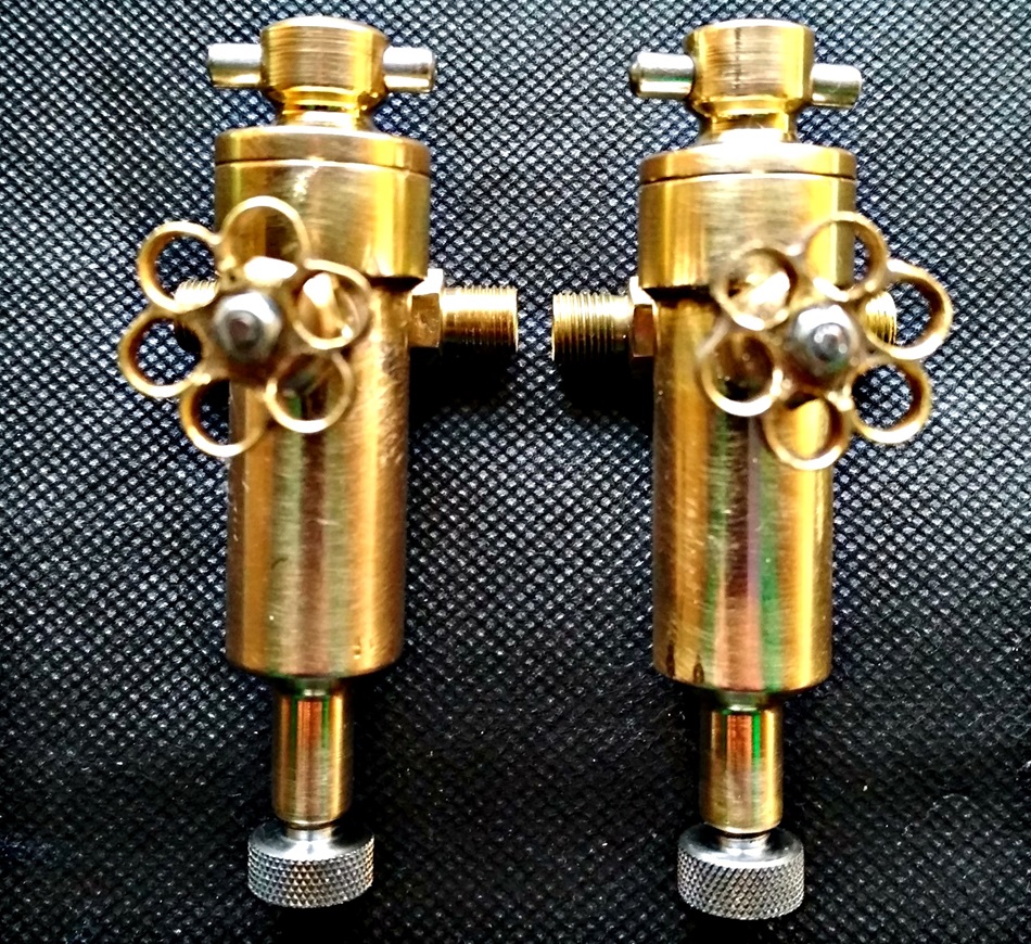
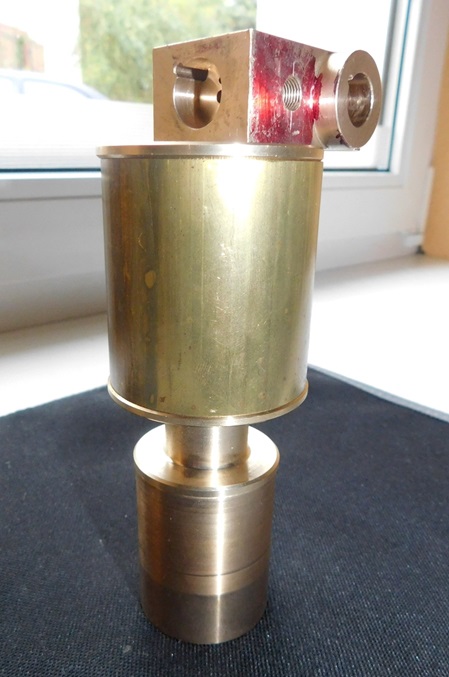
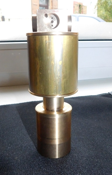
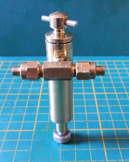
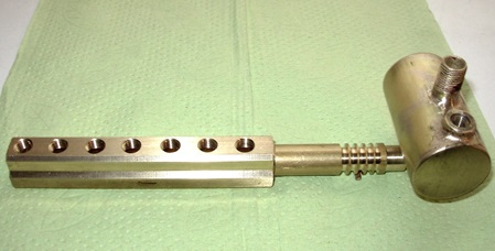
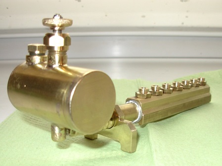
Dampfstrahl-Öler (Kondensations-Öler) für die Pumpen.
Die Pumpen müssen während des Betriebes mit Öl versorgt werden. Dazu habe ich Dampfstrahlöler gebaut.
Die Funktion ist ganz simpel. Der Öler wird in die Dampfzuleitung zur Pumpe eingebaut. Durch eine kleine Bohrung, die mit einem Nadelventil eingestellt werden kann, gelangt Dampf in den Öler und kondensiert an der kalten Ölerwandung zu Wasser. Da Wasser bekanntlich schwerer als Öl ist, sinkt das Wasser nach unten und verdrängt das Öl in die Dampfzuleitung. Dort wird das Öl mit dem Dampfstrom zur Pumpe befördert.
Ab und an muss man das Wasser über eine Ablassschraube aus dem Öler entfernen und frisches Öl nachfüllen.
Steam jet oiler (condensation oiler) for the pumps.
The pumps must be supplied with oil during operation. I have built steam jet oilers for this purpose.
The function is very simple. The oiler is installed in the steam pipe to the pump. Steam enters the oiler through a small hole, which can be adjusted with a needle valve, and condenses to water on the cold oiler wall. As water is known to be heavier than oil, the water sinks to the bottom and displaces the oil into the steam pipe. There, the oil is transported to the pump with the steam flow.
From time to time, the water must be removed from the oiler via a drain plug and fresh oil must be added.
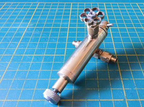
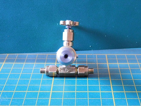
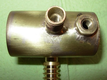
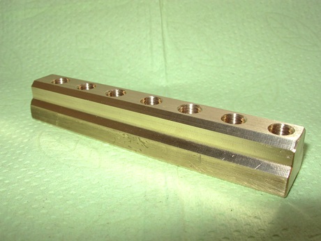
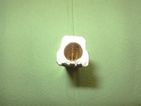
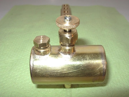
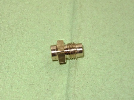
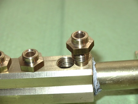
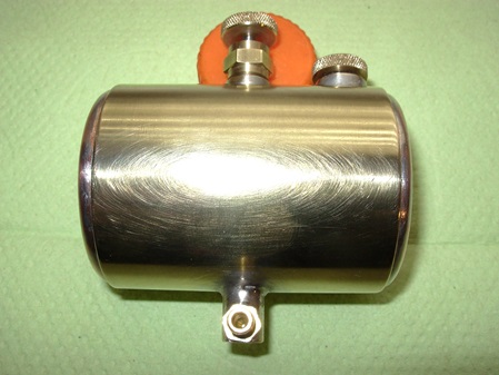
Body, drain plug and screw plug of an oiler.
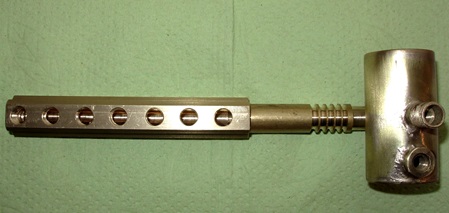
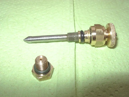
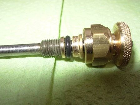
Finished lubricator with dosage spindle, screw plug and soldered T-connection.
29.05.2019
Große Westinghouse Dampfpumpe.
Ein Clubkamerad hat mich überredet, ihm zwei Dampfpumpen für große Lokomotiven zu bauen.
Die Pumpen haben die Größe wie ich sie vor über 20 Jahren für die Lok "Gustavsburg" gebaut habe.
Dampfkolben-Durchmesser 30mm.
Wasserkolben-Durchmesser 16mm.
Kolbenhub 40mm.
Fördervolumen theoretisch 15ccm je Doppelhub.
Large Westinghouse Steam Pump.
A club member has asket me to build him two steam pumps for large locomotives.
The pumps are the size I built over 20 years ago for the locomotive "Gustavsburg".
Steam cylinder diameter 30mm.
Water cylinder diameter 16mm.
Piston stroke 40mm.
Theoretical pumping volume 15ccm per double stroke.
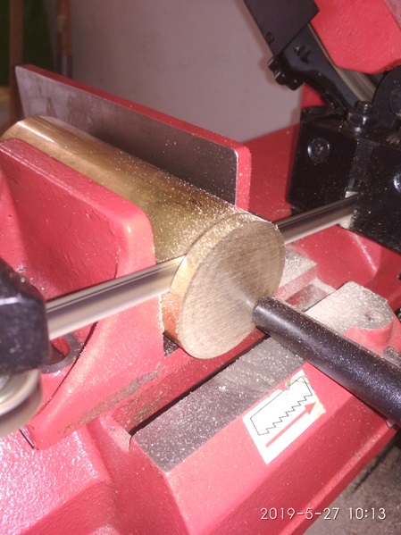
First, the material was cut on the band saw.
The first parts are almost finished.
Some drillings are still missing.
11.10.2019
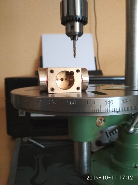
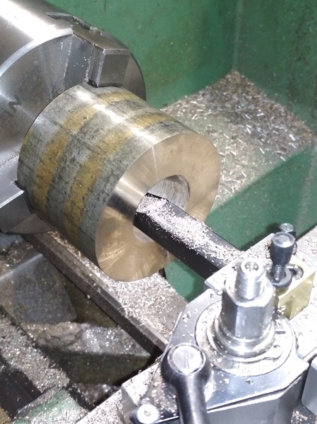
Nach fast 5 Monaten hat mir der Auftraggeber endlich ein Stück Bronce mit einem Durchmesser von 65mm übergeben. Jetzt konnte ich den Steuerkopf und den Dampfzylinder fertigen.
Daraus habe ich jeweils die Zylinder und auch zwei Scheiben für den Steuerblock geschnitten. Meine Bandsäge hat mir dabei gute Dienste geleistet.
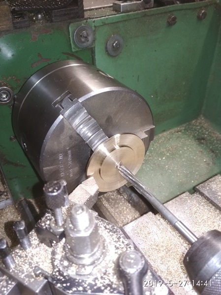
Die Scheiben für die Steuerblöcke habe ich auf der Drehmaschine beidseits geplant und im Anschluss daran auf der Bandsäge zu einem Quadrat von 48mm zurecht geschnitten.
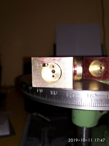
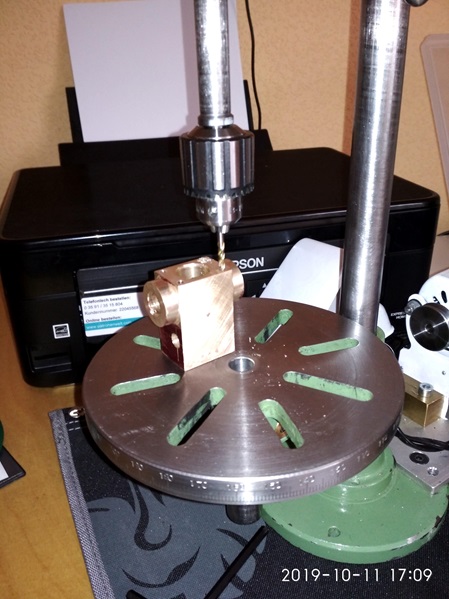
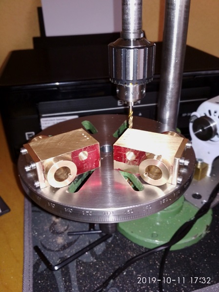
Auf der Fräsmaschine wurden dann diese Flächen überfräst, so dass alle Flächen im Rechten Winkel zueinander stehen. Nach der Fräsarbeit hatte ich zwei Klötze mit den Maßen 45 x 45 x 22mm.
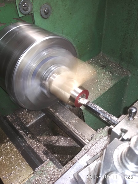
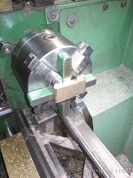
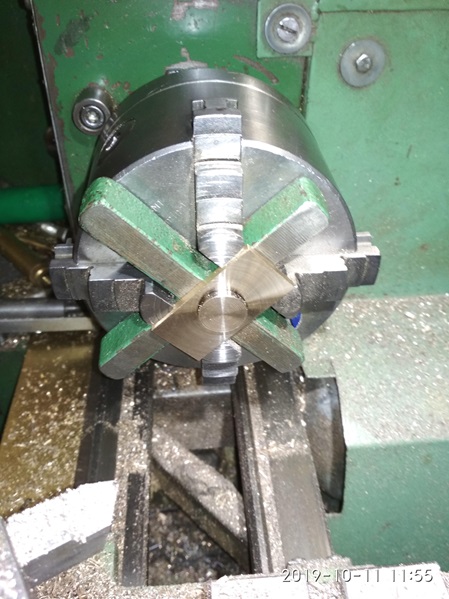
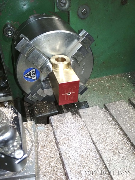
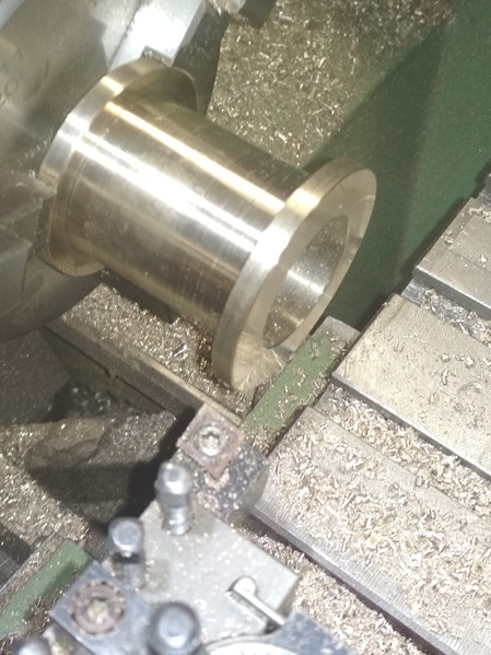
Nun ging es auf die Drehmaschine, um mit dem einzel verstellbaren Vierbackenfutter die seitlichen Zylinderansätze anzudrehen.
Bei dieser Gelegenheit wurde auch gleich die Bohrung für den Haupt-Steuerschieber gefertigt.
Es kommen nun noch ein paar Bilder von der Dreherei.
After almost 5 months, the client finally gave me a piece of bronze with a diameter of 65mm. Now I could make the control head and the steam cylinder.
From this I cut each of the cylinders and also two discs for the control block. My band saw served me well for this.
I planned the disks for the control blocks on both sides on the lathe and then cut them to a square of 48mm on the bandsaw.
On the milling machine, these surfaces were then milled over, so that all surfaces are at right angles to each other. After the milling work I had two blocks with the dimensions 45 x 45 x 22mm.
Now it went to the lathe to turn the lateral cylinder lugs with the individually adjustable four-jaw chuck.
On this occasion, the bore for the spinning piston was also made.
Here are a few more pictures from the lathe.
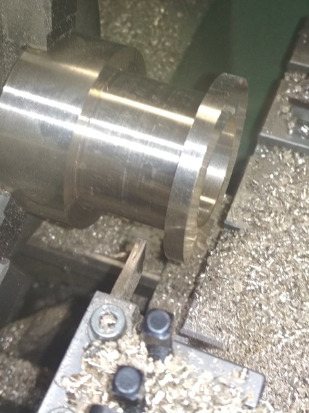
After turning the first cylinder shoulder on the individually adjustable four-jaw chuck, I was able to turn the part over and make the other side in the center-clamping four-jaw chuck.
Here I am just about to make the bore for the spinning piston.
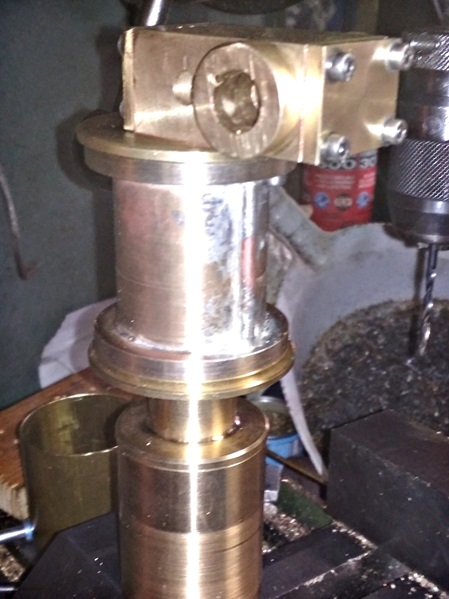
Here is the set-up for producing the chamber for the slides. The valve holes were drilled beforehand.
This is the sling piston chamber. The holes for the cover fixing have also been drilled.
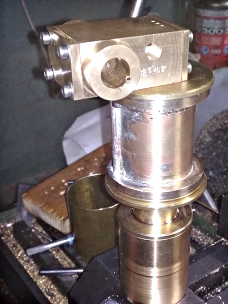
The control heads are designed in mirror image. Once for right and once for left mounting.
Here the steam inlet side.
The covers on the centrifugal piston chamber are also already attached.
12.10.2019
Heute habe ich die Steuerköpfe fertig gestellt. Dazu wurden die oberen Pumpendeckel an die Steuerköpfe angepasst und verschraubt.
Im Anschluss wurden die Verbindungsbohrungen gefertigt.
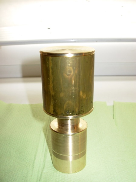
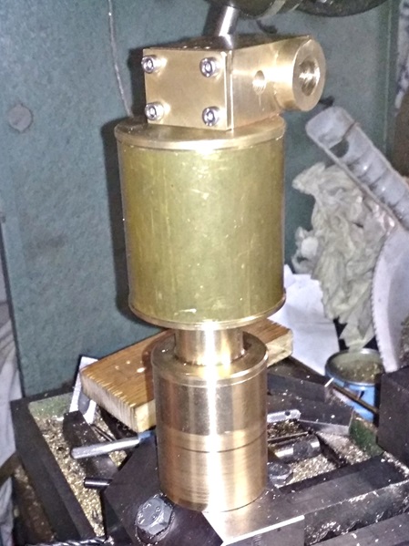
Ich hab mal die Teile grob zusammengestellt, damit man einen Eindruck von den Proportionen bekommt.
Today I finished the control heads. For this purpose, the upper pump covers were adapted to the control heads and screwed.
After that, the connecting holes were made.
I have roughly put together the parts so that you get an impression of the proportions.
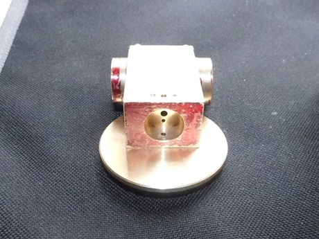
Control head with screwed cover.
The screws are later replaced by countersunk screws.
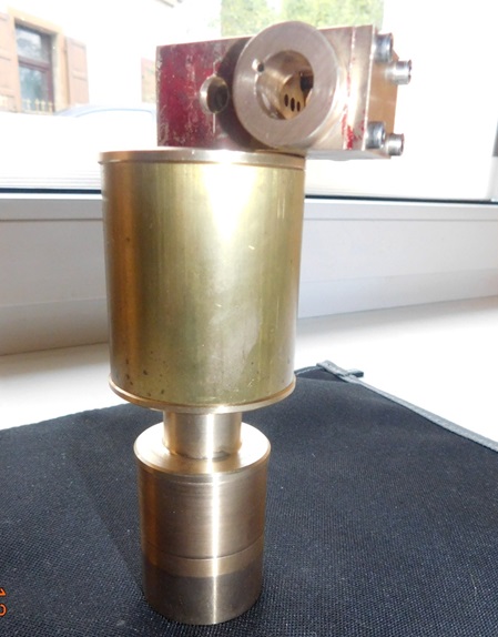
The upper diameter is 52mm.
The total height will be about 160mm.
So, nun aber zu dem abgebrochenen Bohrer.
Der steckte natürlich noch im Steuerblock. Ein Versuch, ihn mit einem Hartmetallfräser heraus zu bohren, schlug fehl. Ich habe dann den kompletten Steuerblock auf die Drehmaschine genommen und auszentriert. Den inneren Kern hab ich stufenweise mit verschiedenen Bohrern aufgebohrt bis die Bohrerfragmente herausgebrochen waren.
Im Anschluss wurde der Steuerblock auf 16mm ausgedreht und mit der Presse ein Füllstück aus Bronce mit Loctite eingepresst. Anschließend wurde alles nochmals Überdreht und die Steuerbohrungen erneut gefertigt.
So, now to the broken off drill bit.
Of course, it was still stuck in the control block. An attempt to drill it out with a carbide cutter failed. I then took the complete control block to the lathe and centered it. I drilled out the inner core in stages with different drills until the drill fragments were broken out.
Then the control block was turned out to 16mm and a bronze filler was pressed in with Loctite. Afterwards, everything was turned over again and the control bores were made again.
15.10.2019
Heute war der erste Zylinder an der Reihe.
Aus einer Bronze-Welle, mit 65mm Durchmesser, wurde der Zylinder gefertigt.
Zunächste wurde die Zylinderbohrung eingebracht. Geplant, zentriert, mit 10mm vorgebohrt und im Anschluss daran mit dem Bohrstahl stufenweise auf genau 29,5mm ausgedreht.
Die letzten 5/10mm wurden mit dem Feinvorschub augedreht.
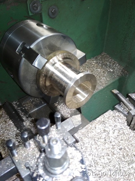
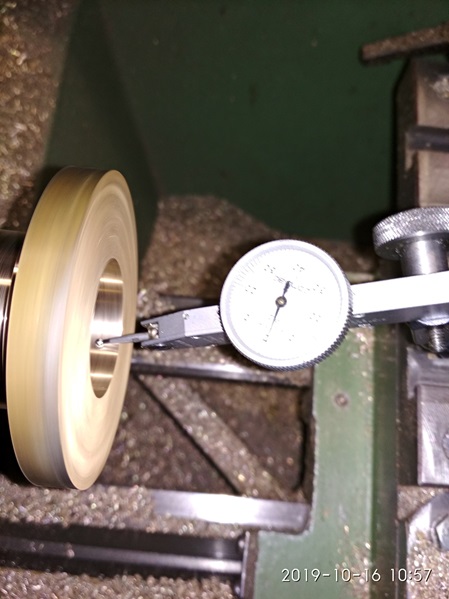
Danach wurde die erste Hinterdrehung, zur Gestaltung des Flansches gemacht. Das Teil wurde umgespannt und der Rundlauf mit der Messuhr an der fertigen Bohrung ausgerichtet. Dann kam der zweite Flansch dran.
Für die Verbindung vom Steuerblock zur unteren Dampfkammer, musste noch ein Verbindungsrohr eingelötet werden. Die entsprechende Bohrung wurde angerissen und von beiden Seiten mit 4,1mm gebohrt. Diese Bohrung wurde auf den Steuerblock übertragen und der Dampfkanal in den Steuerblock gebohrt.
Im Anschluss wurde ein 4mm Kupferrohr weich eingelötet. Dazu verwende ich Weichlotpaste und zusätzlich Flussmittel und auch noch Installationslot als Zusatz. Das Weichlot hat eine Schmelztemperatur von ca.270°C, das reich allemal für die thermischen Belastungen, die hier auftreten.
Die Stirnflächen wurden gesäubert.
Today it was the turn of the first cylinder.
The cylinder was made from a bronze shaft with a diameter of 65mm.
First, the cylinder bore was drilled. Planned, centered, predrilled with 10mm and then turned out step by step with the drill steel to exactly 29.5mm.
The last 5/10mm were turned out with the fine feed.
After that, the first back-turn was made to shape the flange. The part was reclamped and the runout aligned with the finished bore using the dial indicator. Then came the second flange.
For the connection from the control block to the lower steam chamber, a connecting tube had to be soldered in. The corresponding hole was scribed and drilled from both sides with 4.1mm. This hole was transferred to the control block and the steam channel was drilled into the control block.
Subsequently, a 4mm copper tube was soft soldered in. For this I use soft solder paste and additional flux and also installation solder as an additive. The soft solder has a melting temperature of about 270°C, which is sufficient for the thermal loads that occur here.
The front surfaces were cleaned.
The first back-turn, the first flange is formed.
From the other side.
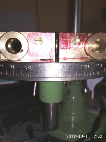
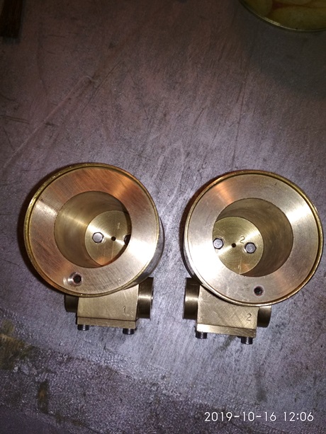
Each pump gets a serial number from me. This pump has the number: 201902
16.10.2019
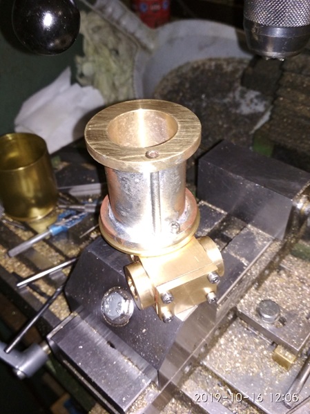
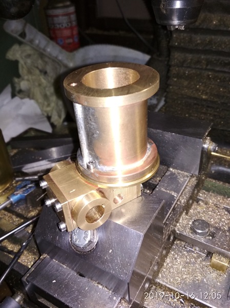
Heute war der zweite Zylinder dran.
Today it was the turn of the second cylinder.
The operating sequence was exactly the same as for the first cylinder.
After one side was finished, the other side was aligned and machined with the fine probe.
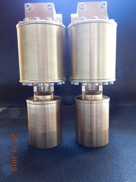
25.10.2019
Ich bin mittlerweile etwas weiter gekommen.
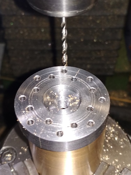
Alle Befestigungsbohrungen des Dampfzylinders gebohrt und Gewinde geschnitten. Dazu habe ich mir eine Bohrschablone aus Stahl gefertigt. Sie ist zum Bohren des Zylinders, der Deckel und der Oberseite der Laterne.
Die Befestigungsbohrungen von Deckel oben und Steuerblock habe ich auch angesenkt und Edelstahl-Senkschrauben verbaut.
Der Verbindungskanal vom Verbindungsrohr zum unteren Dampfraum wurde eingefräst.
Zwischen allen verschraubten Flächen werden später geölte Papierdichtungen gelegt.
Laterne angepasst und Befestigungsbohrungen gefertigt. Ausschnitt für die Stopfbuchsen eingearbeitet.
Schließlich das Ganze einmal zusammengeschraubt.
I have made some progress in the meantime.
Drilled all mounting holes of the steam cylinder and cut threads. For this purpose, I made myself a drilling template out of steel. It is for drilling the cylinder, the cover and the top of the lantern.
I also countersunk the mounting holes of the top of the lid and the control block and installed stainless steel countersunk screws.
The connecting channel from the connecting tube to the lower steam space was milled.
Oiled paper gaskets will be placed between all screwed surfaces later.
Lantern adapted and mounting holes made. Cutout for the stuffing boxes made.
Finally, the whole thing screwed together once.
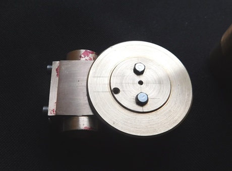
The lower cylinder cover is screwed to the lantern.
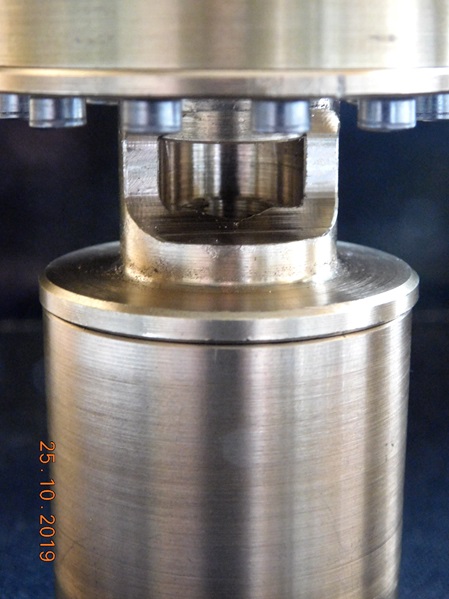
Cutout on the lantern for adjusting the packed glands.
Die nächste Baustelle ist der Pumpenzylinder.
Für die Bohrungen werde ich auch eine Bohrschablone fertigen.
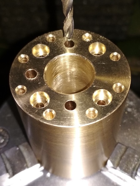
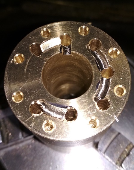
An den Stirnseiten werden einschließlich der Zylinderbohrung 16 Bohrungen eingebracht. (Befestigungsbohrungen, Verbindungskanäle und Ventilkammern).
Der Pumpenzylinder ist durchlöchert wie ein Schweizer Bergkäse.
The next construction site is the pump cylinder.
I will also make a drilling template for the holes.
16 holes will be drilled on the end faces, including the cylinder hole. (Mounting holes, connecting channels and valve chambers).
The pump cylinder is perforated like a Swiss mountain cheese.
29.10.2019
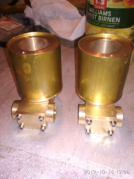
Heute wurde der Wasser-Pumpenzylinder und der untere Deckel ferig gestellt.
Für die vielen Bohrungen im Pumpenzylinder habe ich die angefertigte Bohrschablone verwendet, mit der alle Bohrungen der Wasser-und Verbindungskanäle, sowie die Befestigungsbohrungen angebohrt werden konnten.
Today the water pump cylinder and the lower cover were finished.
For the many holes in the pump cylinder, I used the drilling template that I had made, which allowed me to drill all the holes for the water and connecting channels, as well as the mounting holes.
Drilling template on the pump cylinder.
This drilling template was used to drill the water side of the lantern and also the lower pump cover.
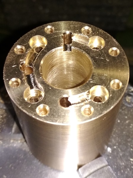
The connecting channels are drilled here. The valve chambers are also already drilled.
Here the upper connecting channels to the holes are milled.
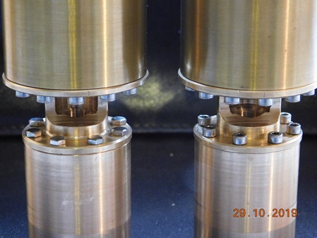
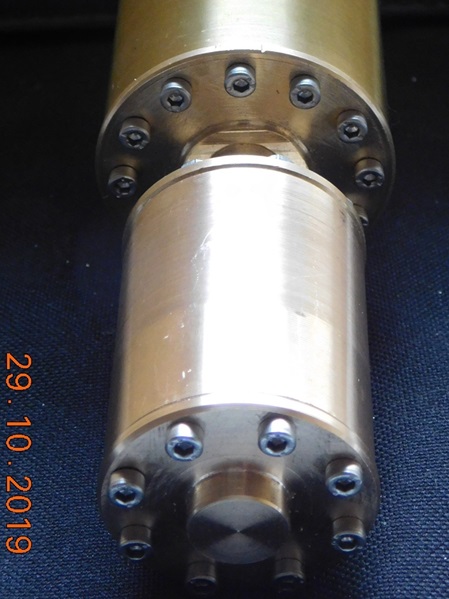
Here everything is assembled. I will fasten all pump cylinders with hexagonal bolts. There is little room between the steam cylinder and the pump cylinder for an Allen wrench.
Es fehlen noch die seitlichen Zu- und Abgangsbohrungen für das Wasser.
Demnächst geht es mit den Innereien der Pumpe weiter.
The side inlet and outlet holes for the water are still missing.
Soon we will continue with the innards of the pump.
31.10.2019
Ich bin wieder etwas weiter gekommen.
Die Zu-und Abgangsanschlüsse an der Pumpe habe ich eingebohrt.
Den Wasser- und Dampfkolben, sowie die Kolbenstange habe ich gefertigt.
I have made some progress again.
I drilled the inlet and outlet connections on the pump.
I made the water and steam pistons and the piston rod.
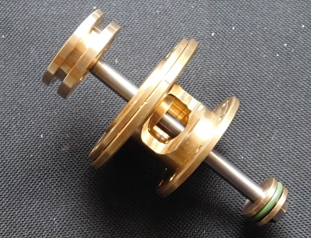
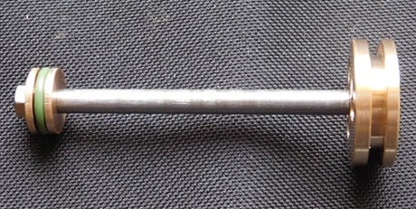 Kolbenstange mit beiden Kolben. Der Dampfkolben ist aus zwei Teilen zusammen gebaut, da wird später ein Mantelkolbenring seinen Dienst tun. Im Wasserkolben ist ein Viton O-Ring verbaut. Die Kolben haben in ihren Bohrungen jeweils 5/100mm Spiel und wurden, auf der Kolbenstange montiert, überdreht.
Der Dampfkolben ist auf die Kolbenstange mit Loctite 648 aufgeschraubt.
Piston rod with both pistons. The steam piston is made up of two parts, and a skirt piston ring will be used later. A Viton O-ring is installed in the water piston. The pistons each have 5/100mm clearance in their bores and were over-torqued when mounted on the piston rod.
The steam piston is screwed onto the piston rod with Loctite 648.
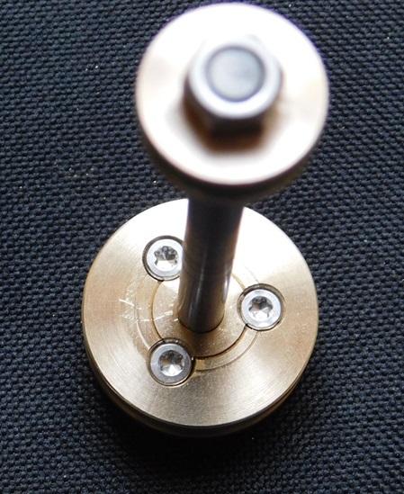
The lower part of the steam piston is fixed with 3 stainless steel countersunk screws. During final assembly, this part is installed with sealant.
The inlet and outlet connections are also installed. Connection thread is M8 x 1mm. Intended for the connection of a 5mm pipeline.
02.11.2019
Heute habe ich einige Einzelteile für den Windkessel hergestelt.
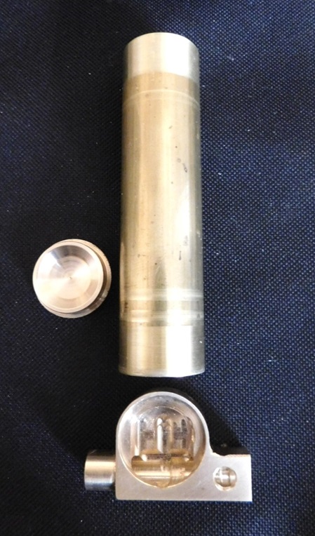
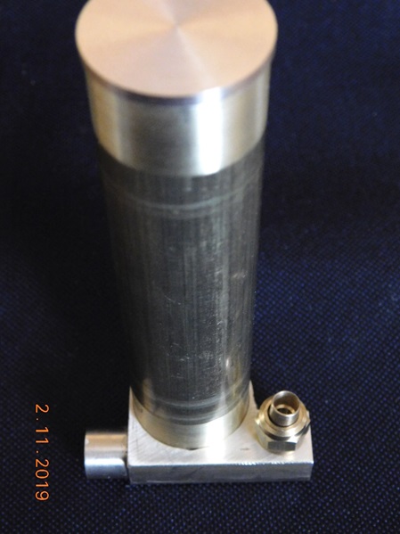
Das Unterteil wurde aus einer Messing- Flachstange 30 x 12 mm herausgefräst.
Der Kessel selbst ist aus einem Messingrohr 25 x 1 gefertigt. Der Deckel ist ebenfalls aus Messing.
Die Einzelteile werden mit Silberlot zusammen gelötet.
Today I made some parts for the air vessel.
The lower part was milled out of a brass flat bar 30 x 12 mm.
The boiler itself is made from a brass tube 25 x 1. The lid is also made of brass.
The individual parts are soldered together with silver solder.
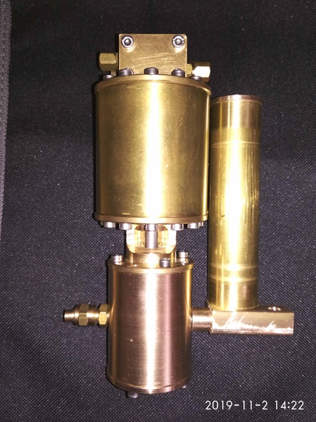
All parts plugged together. On the right is the connection for the water outlet from the pump. The air vessel is attached to the water cylinder by a long banjo bolt.
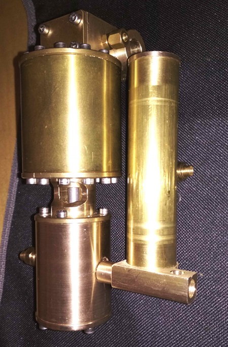
Die Konstruktion, zur Befestigung und Wasserführung des Windkessels, habe ich geändert. Die erste Ausführung (siehe oben) hat die Pumpe zu breit werden lassen.
Oft sitzt die Pumpe in der Nähe der Rauchkammer und das Kesselspeiseventil in der Mitte des Langkessels. Die Druckleitung muß dann in einem Bogen zurück verlegt werden.
Bei der Neukonstruktion wird diese Umlenkung innerhalb des Windkessels erfolgen.
Ich musste ein neues Unterteil herstellen. Die Verbindung-Bohrungen wurden vor der Verlötung im Unterteil angebracht und sind von Außen nicht zu erkennen. Es gibt keine Blind-Bohrungen, die später verschlossen werden mussten.
I have changed the design, for mounting and water guidance of the air vessel. The first design (see above) made the pump too wide.
Often the pump sits near the smoke chamber and the boiler feed valve in the middle of the long boiler. The discharge line must then be routed back in a bend.
In the new design, this bend will be inside the air receiver.
I had to fabricate a new bottom section. The connection holes were made in the lower part before soldering and cannot be seen from the outside. There are no blind holes that had to be closed later.
The pressure line connection to the boiler feed valve is located behind the pump cylinder and goes in the same direction as the suction line connection.
The air vessel is located, laterally offset to the rear and is attached to the pump cylinder via a stainless steel hollow screw.
20.11.2019
Der Haupt-Steuerschieber und der Hilfs-Steuerschieber sind mittlerweile auch fertig gestellt.
Der Haupt-Steuerschieber besteht aus insgesamt 3 Teilen.
Den zwei Teilen der Kolben und einem Muschelschieber.
Der Hilfs-Steuerschieber besteht aus zwei Teilen.
Der Muschelschieber und ein Mitnehmer mit Schleppstange, die vom Dampfkolben bewegt wird
Der Mitnehmer ist noch in Arbeit.
The main control slider and the auxiliary control slider have also been completed in the meantime.
The main spool consists of a total of 3 parts.
The two parts of the pistons and a shell valve.
The auxiliary spool consists of two parts.
The shell valve and a driver with a drag rod, which is moved by the steam piston.
The follower is still in progress.
The two pistons of the skin control valve.
The piston sealing rings are made of Teflon and are slotted at approx. 45°, they are underlaid with Viton O-rings.
Die Einzelteile der Pumpe sind nun fertig. Es kann an den Zusammenbau gehen und den ersten Probelauf.
Alle Dichtflächen wurden mit geölten Papierdichtungen oder "Hylomar" abgedichtet.
Beim Probelauf war der Wasserzylinder noch nicht montiert.
Mit viel Öl und ordentlich Pressluft startete die Maschine ohne Verzögerung.
Die Pumpe wurde ca. 15 Minuten mit Pressluft betrieben und im Anschluss auf Leckagen untersucht. -Alles dicht-!!
The individual parts of the pump are now ready. It is now time for assembly and the first test run.
All sealing surfaces were sealed with oiled paper seals or "Hylomar".
During the test run, the water cylinder was not yet mounted.
With plenty of oil and proper compressed air, the machine started without delay.
The pump was run for about 15 minutes with compressed air and then checked for leaks. -Everything tight-!!
22.11.2019
Beide Pumpen liefen nach dem Zusammenbau auf Anhieb los.
Zunächst wurde nur der Dampfteil mit Laterne zusammengebaut und ausgerichtet. Der Erste Probelauf war noch ohne Dichtung an der Steuerkammer.
Nach einer Feinjustierung des Steuerschiebers lief die Dampfeinheit los und der Kolben erreichte auch den oberen- sowie den unteren Totpunkt, ohne dass der Kolben an beiden Endlagen an den Deckeln anschlug.
Nach erfolgter Montage von Wasserzylinder mit seinen Saug- und Druckventilen, konnte die gesamte Einheit gestartet werden. Im Dampfteil wurde etwas Öl eingespritzt und dann mit Pressluft beaufschlagt. In den Ansaugtrakt des Wasserzylinders wurde ebenfalls etwas Öl eingespritzt. Die Pumpe startete zunächst etwas widerwillig, aber nach dem das Öl durchgepumpt war, lief die Pumpe in jeder Endstellung zuverlässig los.
Vor der Auslieferung wurde der Wasserteil mit einer Heißen Seifenlaugen- Lösung durchgespült, damit auch die letzten Reste vom Öl beseitigt waren.
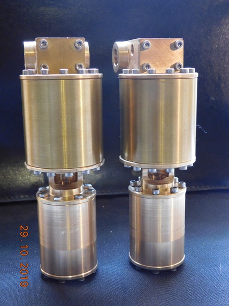
Both pumps started running right away after assembly.
First, only the steam part with lantern was assembled and aligned. The first test run was still without seal at the control chamber.
After fine adjustment of the control spool, the steam unit started running and the piston also reached top and bottom dead center without hitting the covers at either end position.
After assembling the water cylinder with its suction and discharge valves, the entire unit could be started. In the steam section, some oil was injected and then compressed air was applied. Some oil was also injected into the suction section of the water cylinder. The pump started somewhat reluctantly at first, but after the oil was pumped through, the pump started reliably in each end position.
Before delivery, the water section was flushed with a hot soap solution to remove the last remnants of oil.
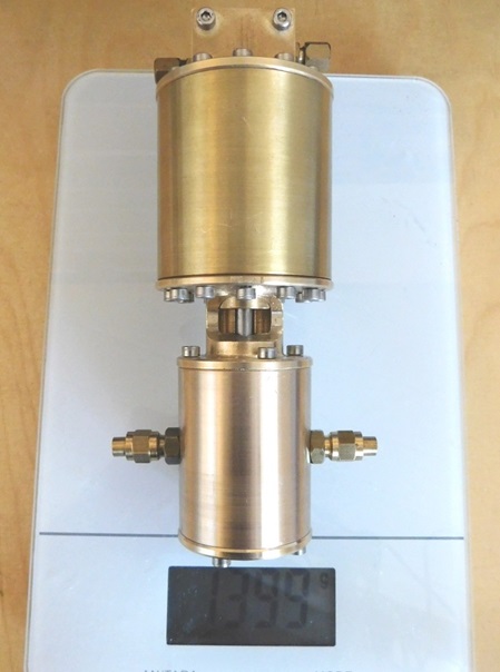
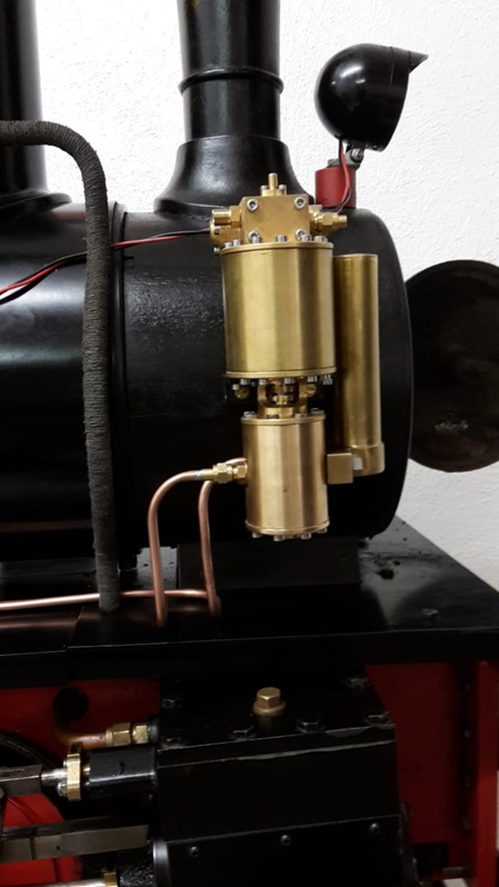
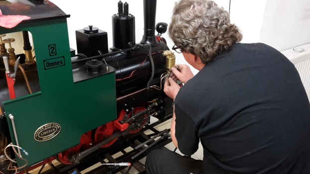
One of the pumps at its destination.
Abschließend noch einige Bemerkungen dazu.
Die Fertigung hat Freude gemacht, auch wenn es sehr Zeitaufwändig war. Ich konnte an den Pumpen einige Änderungen vornehmen. Das Grundkonzept blieb aber gleich und stammte ursprünglich von Herrn Wittmann.
Den Druck-Windkessel und einen Befestigungswinkel habe ich gleich mit angebracht. Die Abmessungen der Dampfversorgung und der Wasserführung wurden gegenüber den ersten Pumpen etwas vergrößert. Der Hauptsteuerschieber bekam einen größeren Durchmesser, das erhöht die Umschalt-Sicherheit. Der Dampfkolben besteht aus zwei Teilen. Das erleichtert die Montage vom Kolbenring.
Die Pumpen wurden ausgiebig getestet. Die Pumpen starten zuverlässig. Der Pumpenzylinder baut ordentlich Druck auf. Bei 2 bar Betriebsdruck entwickelt die Pumpe 5 bar Ausgangsdruck. Rein theoretisch müsste die Pumpe ca. 6 bar Drücken, aber sie leistet auch gleichzeitig Saugarbeit.
Das Flächenverhältnis zwischen Dampfkolben und Wasserkolben beträgt im Abwärtshub 3,5 : 1, im Aufwärtshub 3,9 : 1. Der Unterschied entsteht durch die Kolbenstange, die keine Arbeit verrichtet und einen Durchmesser von 6mm aufweist.
Für eine noch größere Pumpleistung ist bei den Abmessungen auch ein Pumpenkolben von 20mm Durchmesser denkbar.
Für alle die mich nach Plänen fragen wollen -- Es gibt keine Pläne dieser Pumpe bei mir. Es ist alles in meinem Kopf und auf wenig Papier durchkonstruiert worden.
Sicherlich habe ich einige Zeichnungen (es sind eigentlich nur Skizzen) angefertigt, insbesondere vom Steuerkopf und dem Pumpen-Zylinder. Es sollte ja auch alles funktionieren und dicht sein.
Komplette Fertigungszeichnungen gibt es nicht von der Pumpe.
Es sind Einzelstücke.
Verwendete Werkstoffe:
Dampf- sowie Wasser-Zylinder: Bronze
Steuerkammer und Deckel: Bronze
Steuerschieber: Bronze
Laterne: MS 58
Zylinderdeckel: MS 58
Kolben : MS 58
Kolbenstange- Steuerstange und Schleuderkolben: X 20 Cr 13 (1.4021)
Verschraubungen: MS 58
Zylindermantel: MS 63
Schrauben: Edelstahl
Ventile: 4 x Edelstahlkugeln Ø 4 mm
Befestigungswinkel: Stahl
E N D E
Finally, a few remarks about it.
The fabrication was a pleasure, even though it was very time consuming. I was able to make some changes to the pumps. But the basic concept remained the same and originally came from Mr. Wittmann.
I added the pressure-wind boiler and a mounting bracket at the same time. The dimensions of the steam supply and the water guide were slightly enlarged compared to the first pumps. The main control valve got a larger diameter, this increases the switching safety. The steam piston consists of two parts. This facilitates the assembly of the piston ring.
The pumps were tested extensively. The pumps start reliably. The pump cylinder builds up decent pressure. At 2 bar operating pressure, the pump develops 5 bar output pressure. Theoretically, the pump should press approx. 6 bar, but it also performs suction work at the same time.
The area ratio between the steam piston and the water piston is 3.5 : 1 in the downstroke and 3.9 : 1 in the upstroke. The difference is due to the piston rod, which does no work and has a diameter of 6mm.
For even greater pumping power, given the dimensions, a pump piston of 20mm diameter is also conceivable.
For those who want to ask me for plans -- There are no plans of this pump with me. It has all been designed through in my head and on little paper.
Certainly I made some drawings (they are actually only sketches), especially of the control head and the pump cylinder. After all, everything should work and be tight.
Complete production drawings do not exist of the pump.
They are single pieces.
Materials used:
Steam and water cylinder: bronze
Control chamber and cover: bronze
spool: bronze
Lantern: MS 58
Cylinder cover: MS 58
Piston : MS 58
Piston rod- control rod and spinning piston: X 20 Cr 13 (1.4021)
Fittings: MS 58
Cylinder jacket: MS 63
Screws: Stainless steel
Valves: 4 x stainless steel balls Ø 4 mm
Mounting bracket: Steel
E N D E
Westinghouse Dampfpumpe
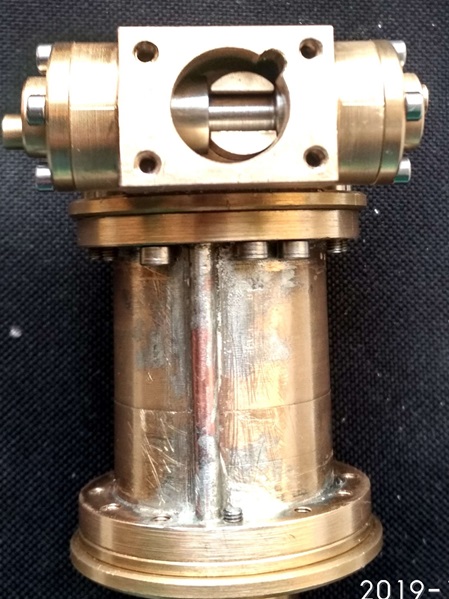
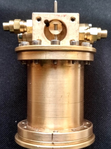
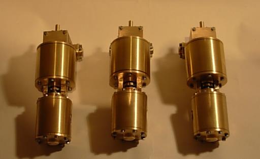
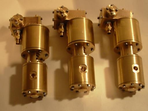
Im Jahr 2007 habe ich eine 2. Auflage von Dampfpumpen vom Typ Westinghouse in einer Kleinserie von 7 Stück hergestellt.
Techn. Daten der Pumpe.
Hub 25mm
Dampfkolben 16mm
Wasserkolben 10mm
Westinghouse steam pump.
In 2007 I made a 2nd edition of Westinghouse type steam pumps in a small series of 7 pieces.
Technical data of the pump.
Stroke: 25mm
Steam piston: 16 mm
Water piston: 10 mm
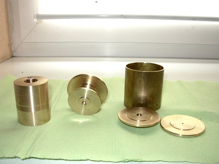
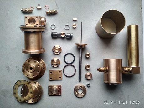
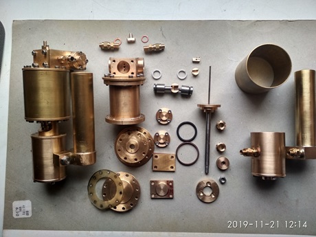
Es folgen einige Bilder der Einzelteile.
Here are some pictures of the parts.
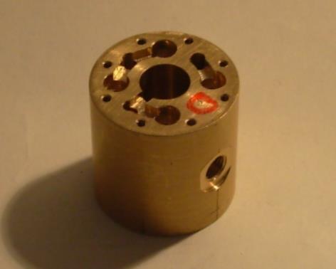
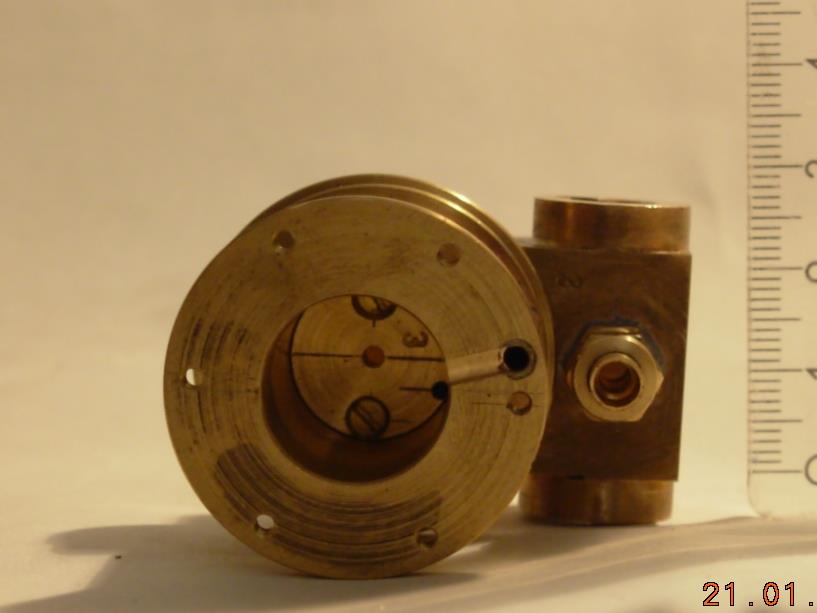
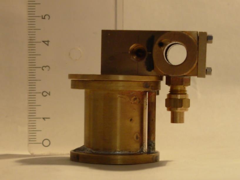
This is the pump part in which the water is pumped.
This is the steam cylinder with the control housing.
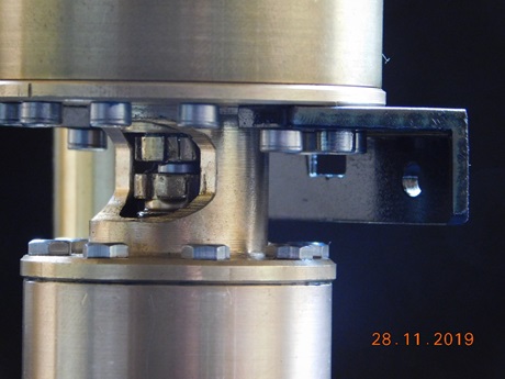
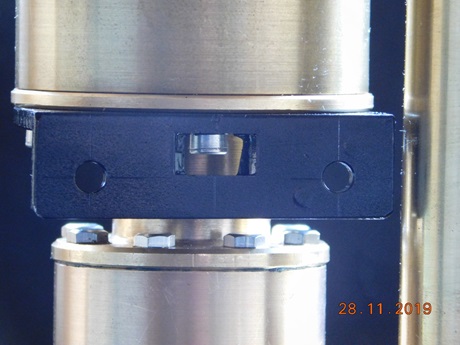
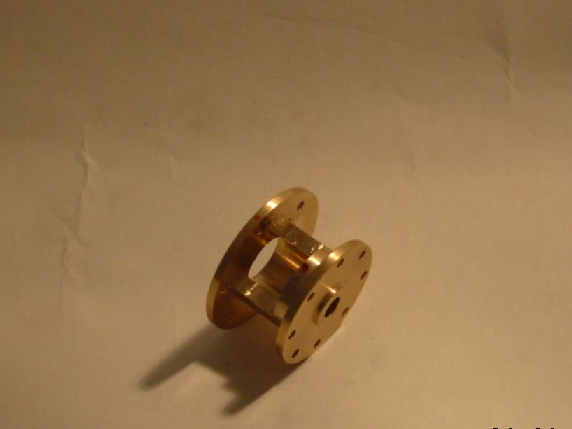
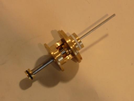
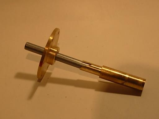
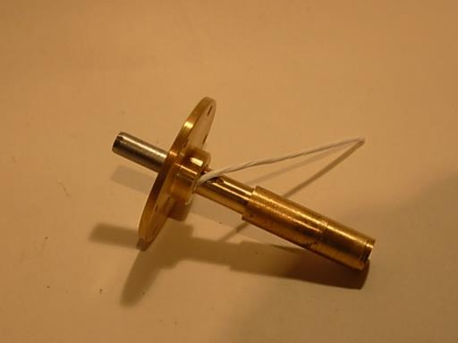
"Lantern" with piston rod and both pistons. The control tow bar protrudes on the right.
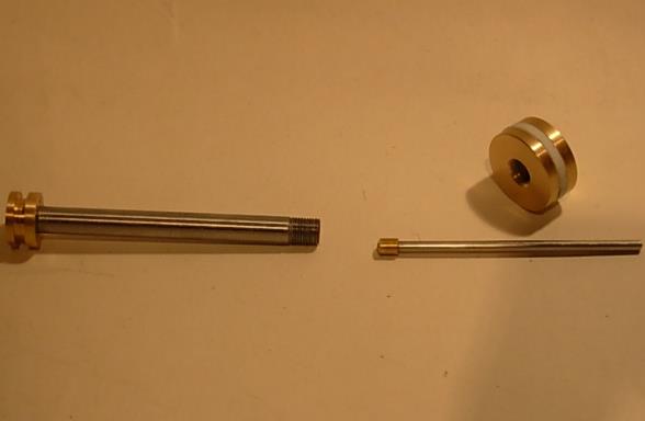
Individual parts of the piston rod.
The piston rod is drilled hollow, and the sliding drag rod runs inside it.
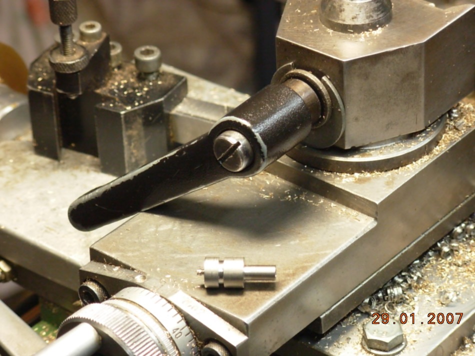
Fabrication of the sling piston.
My old quick-change holder is still installed here.
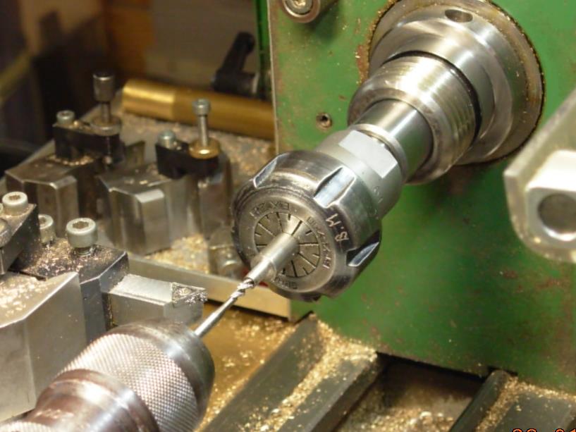
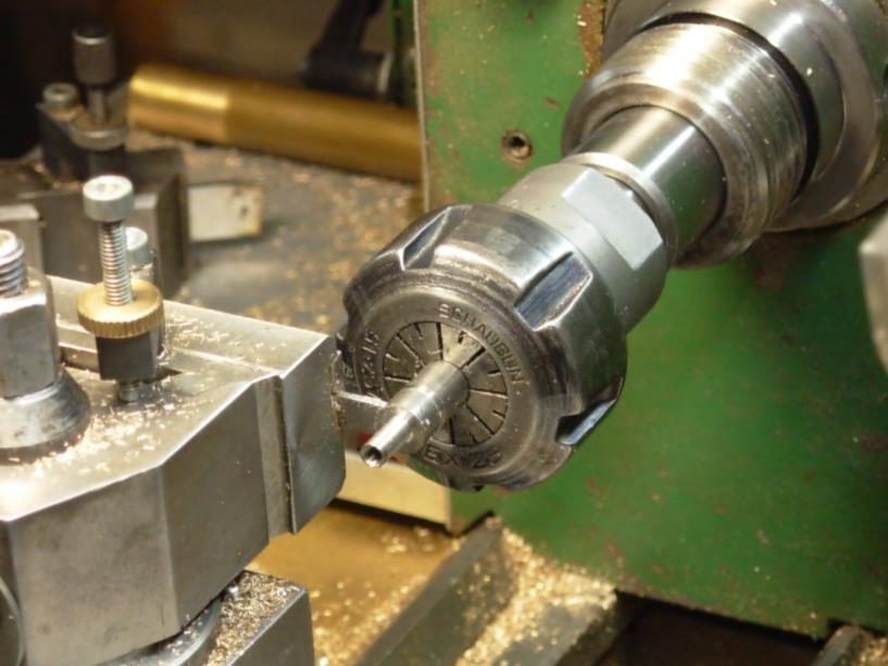
The single parts were manufactured in the collet.
Januar 2009.
Revision einer Dampfpumpe nach 12 Jahren unermüdlicher Tätigkeit.
January 2009.
Revision of a steam pump after 12 years of continuous operation.
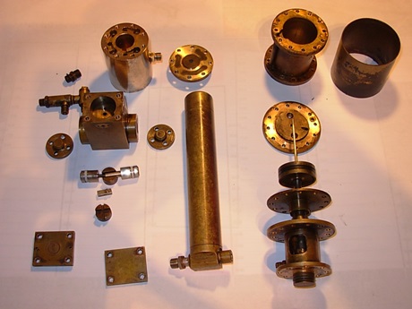 Einzelteile einer Pumpe, die ich vor Jahren für unsere Vereinslok gebaut habe. Die Lok und die Pumpe mußten einer Revision unterzogen werden. Die Pumpe lief zuvor 12 Jahre ohne größere Probleme an der Vereinslok "GUSTAVSBURG"
Auszutauschen waren nur die Stützringe der Schleuderkolben-Dichtungsringe.
Die Pumpe wurde nur gesäubert und genau so wieder zusammengebaut.
Die Patina der Jahre wurde erhalten.
Hier die Daten der Pumpe.
-Dampfkolben-Durchmesser 30mm
-Wasserkolben-Durchmesser 16mm
-Hub 40mm
-Fördervolumen (theoretisch) - je Doppelhub ca. 15ccm Wasser.
-Schleuderkolben-Durchmesser 8mm Hub 5mm
-Schmierung über extra Freilauf-Schmierpumpe.
-Dampfdruck ab ca. 1 bar.
Revision of a steam pump after 12 years of tireless work.Individual parts of a pump that I built years ago for our club locomotive. The locomotive and the pump had to be overhauled. The pump ran before 12 years without larger problems at the club locomotive "GUSTAVSBURG".
Only the support rings of the centrifugal piston sealing rings had to be replaced.
The pump was only cleaned and reassembled exactly the same.
The patina of the years was preserved.
Here are the data of the pump.
-Steam piston diameter 30mm
-Water piston diameter 16mm
-stroke 40mm
-Delivery volume (theoretical) - per double stroke about 15ccm of water.
-spinning piston diameter 8mm stroke 5mm
-Lubrication via extra free-wheeling lubrication pump.
-Steam pressure from approx. 1 bar.
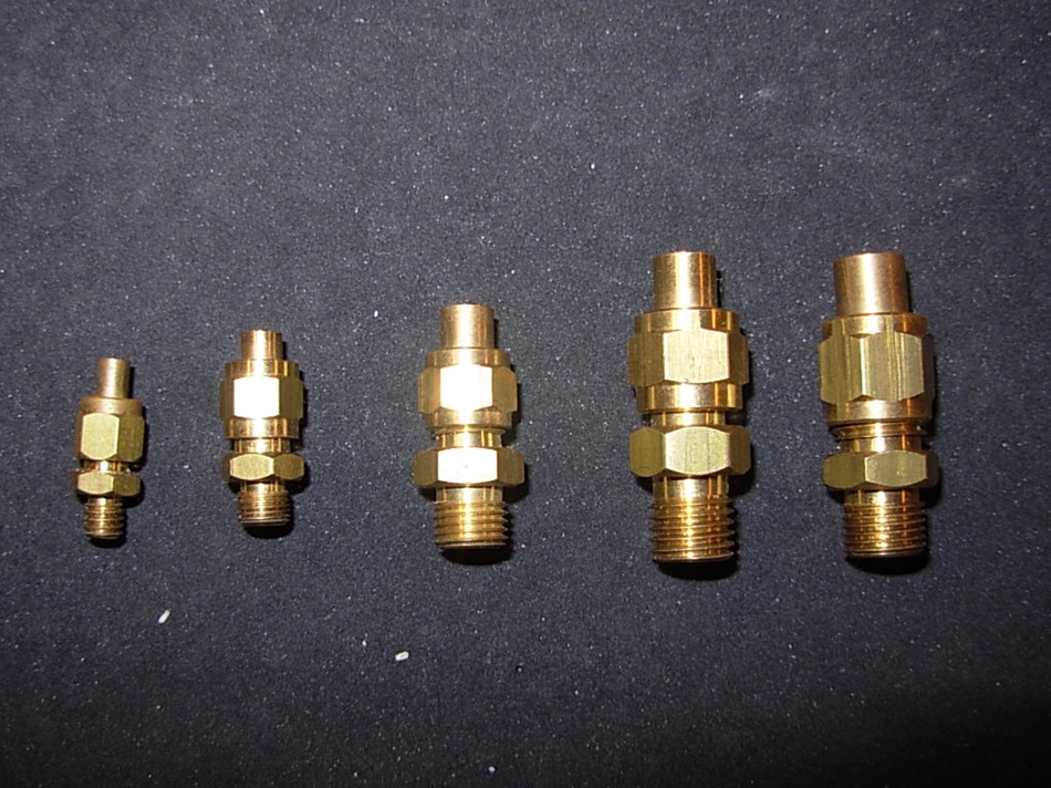
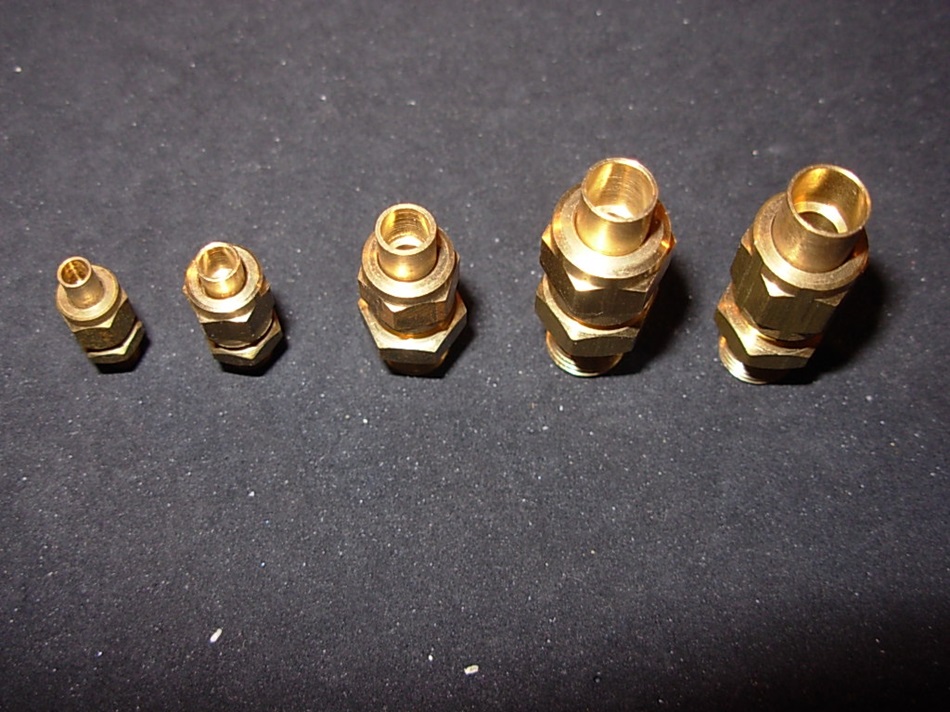
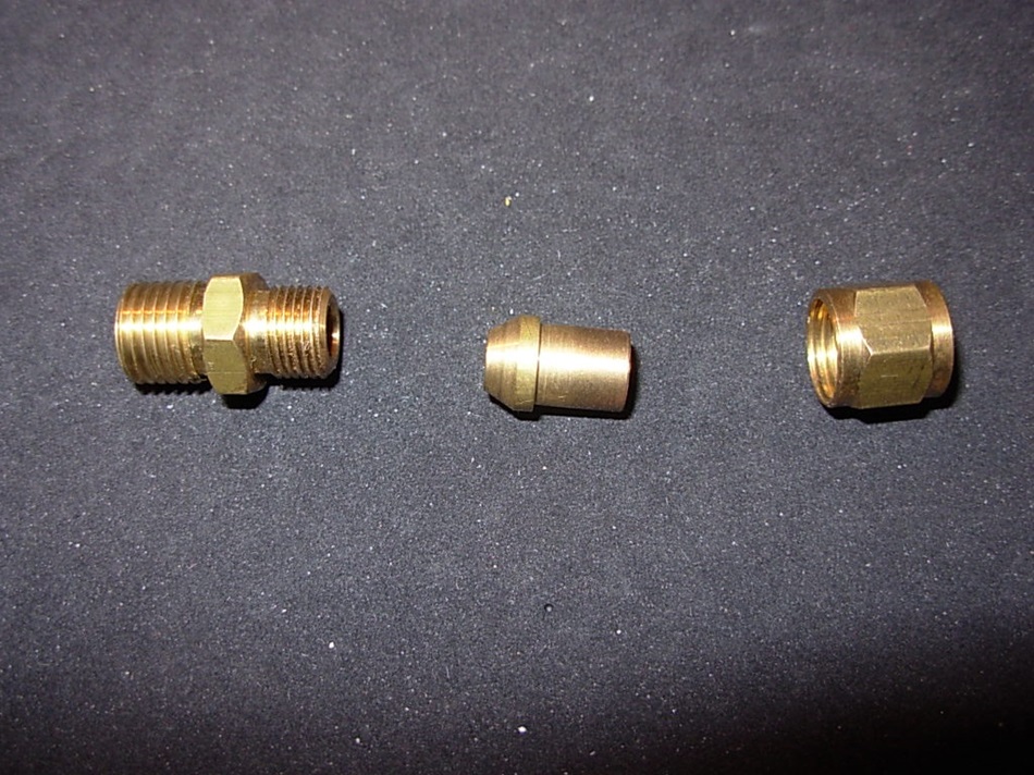
Ventile und Verschraubungen.
Diese Teile kann man bei den bekannten Händlern kaufen.
Ich habe diese selbst gefertigt.
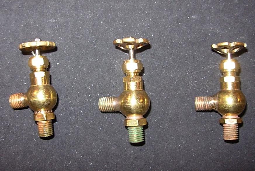
Valves and fittings.
These parts can be bought from the well-known dealers.
I have made these myself.
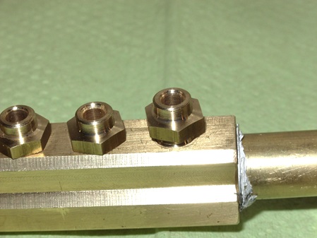
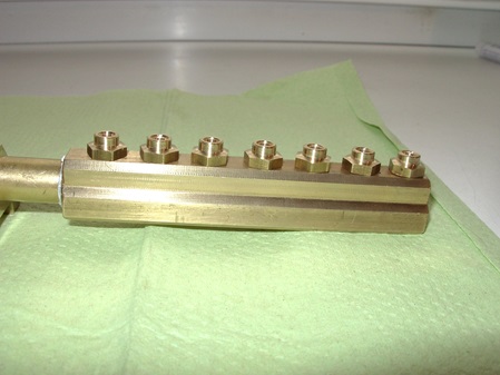
Fittings for tubes 2.5mm; 3mm; 4mm; 5mm; 6mm; (from left to right).
The tubes are inserted into the soldering nipples and soldered with silver solder.
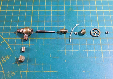
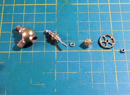
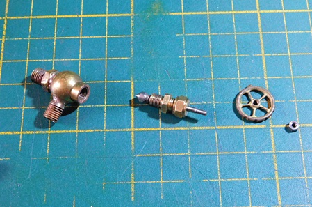
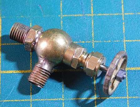
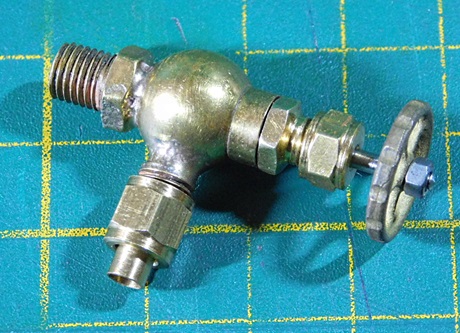
Im Folgenden zeige ich Euch den Werdegang eines Ventiles.
In the following I will show you the production process of a valve.
Here you can see the individual parts. From left to right: valve body, valve spindle, threaded body of the spindle, spindle sealing tape, thrust washer, union nut, handwheel, plastic nut for the handwheel.
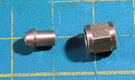
Below: Solder nipple and union nut.
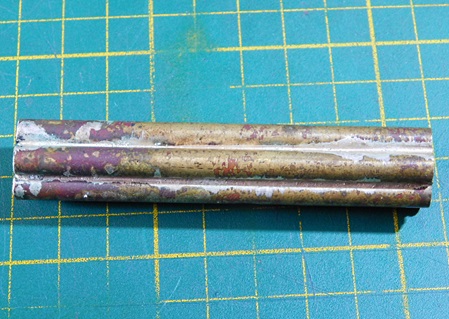
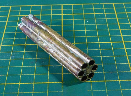
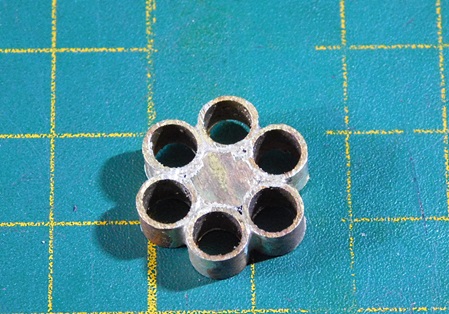
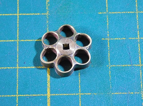
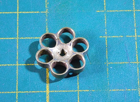
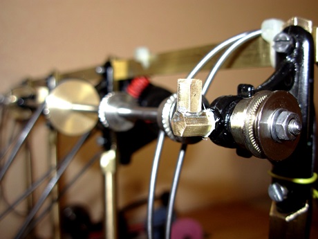
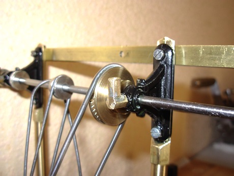
Hier zeige ich ihnen den Werdegang von einem Handrad.
Here I show them the process of a handwheel.
The starting materials are 6 brass tubes and a hexagonal brass rod. These are soldered with silver solder.
Outer diameter of the tubes and of the hexagonal bar, 6 mm each.
First, one side is machined and the square is broached.
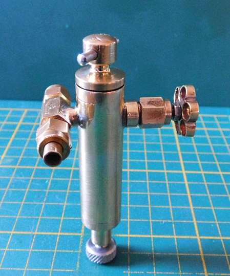
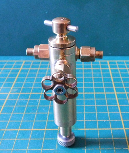
Dampfstrahl-Öler
Dieser Dampfstrahl-Öler ist für kleine Pumpen oder Dampfmaschinen gedacht.
Steam displacement oiler
This steam jet oiler is designed for small pumps or steam engines.
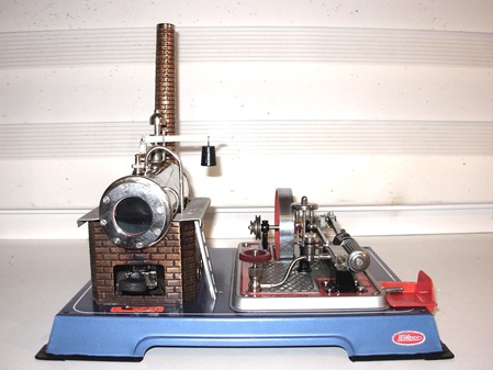
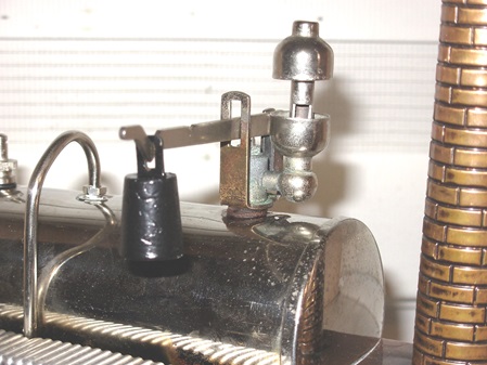
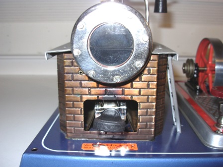
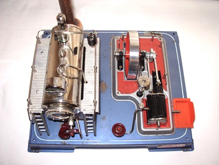
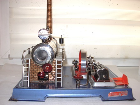
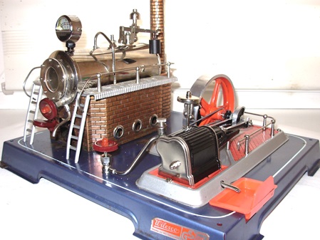
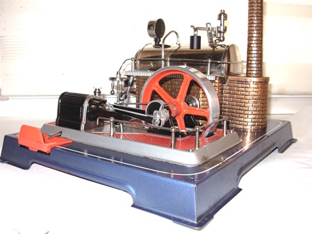
Wilesco Dampfmaschine D16.
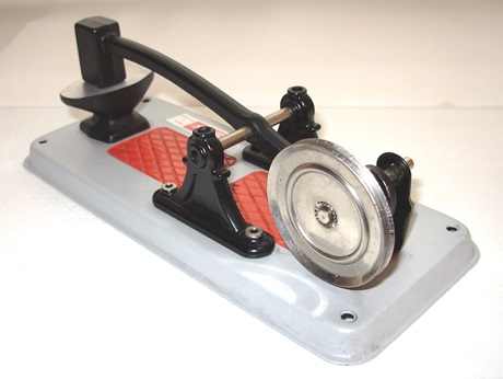
Für meinen Enkel habe ich eine Dampfmaschine von Wilesco erstanden.
Leider fehlen noch einige Teile daran, aber ansonsten ist die Maschine in einem guten Zustand.
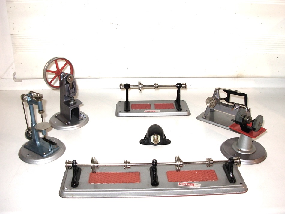
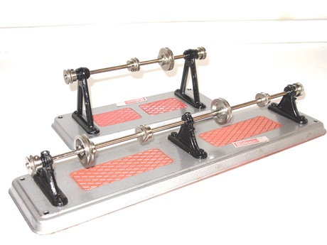
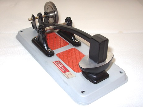
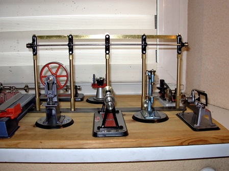
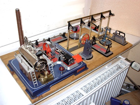
Die Anlage mit Transmission wird auf ein Grundbrett gebaut. Die Antriebs-Modelle werden auf einem seperaten Grundbrett aufgebaut.
Bevor die Anlage unter Dampf geht, werde ich sie ausführlich mit Pressluft testen. Der maximale Druck beträgt 1,5 Bar.
Da wird im Laufe der Zeit sicherlich noch das eine oder andere Modell zum Antreiben hinzu kommen.
Wilesco steam engine D16.
For my grandson I bought a steam engine from Wilesco.
Unfortunately some parts are still missing on it, but otherwise the engine is in good condition.
The layout with transmission is built on a base board. The drive models will be built on a separate base board.
Before the plant goes under steam, I will test it extensively with compressed air. The maximum pressure is 1.5 bar.
In the course of time, there will certainly be one or the other model to drive.
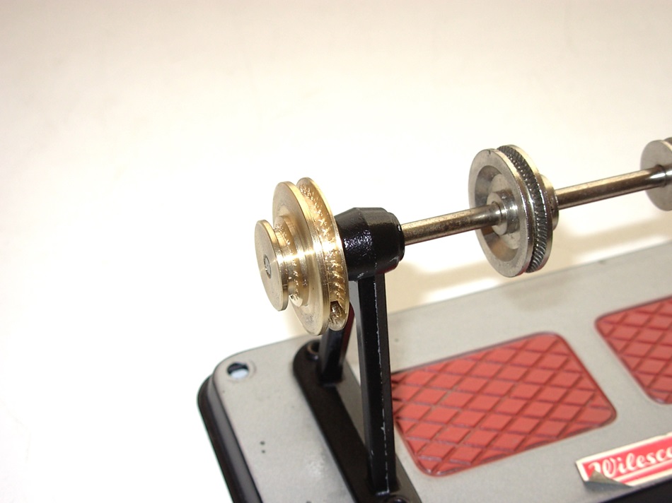 Einige Antrieb-Scheiben habe ich selbst hergestellt.
Mehr dazu im Beitrag "Kleine Basteleien"
16.01.2019
Spiritusbrenner für Wilesco Dampfanlage.
Die Beheizung mittels Esbit-Tabletten ist sehr Schmutzintensiv. Nach dem das Esbit abgebrannt ist, hinterlässt das Zeug einen bräunlich-klebrigen Belag, der den Brennerschieber in seiner Aufnahme verklebt.
Ich habe mich dazu entschlossen einen Spiritus-Dochtbrenner zu verwenden.
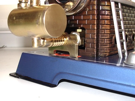
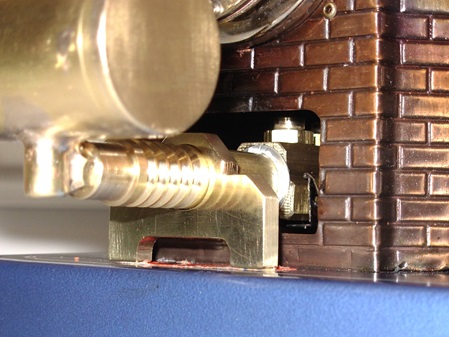
Der Brenner besteht aus einem Schieber, welcher in die Aufnahme vom originalen Brennerschieber passt.
Daran ist ein Vorratsbehälter mit einer Regulierschraube befestigt.
Der Vorratsbehälter wurde mit Silberlot hart gelötet.
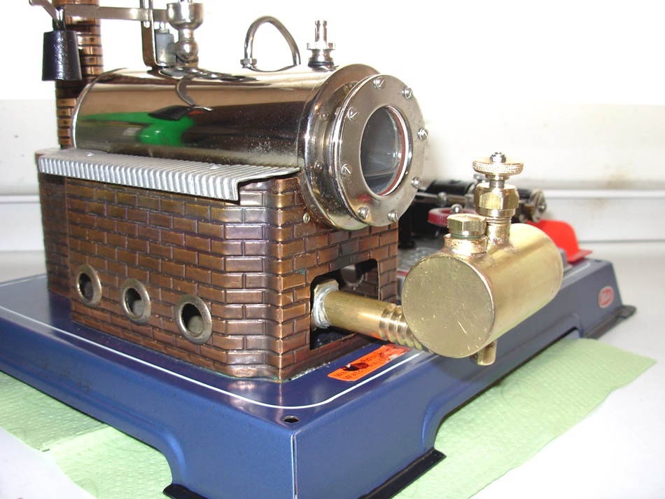
Bilder sagen mehr als viele Worte.
Alcohol burner for Wilesco steam plant.
Heating by means of Esbit tablets is very dirt-intensive. After the Esbit burns off, the stuff leaves a brownish sticky coating that gums up the burner slide in its receptacle.
I decided to use a spirit wick burner.
The burner consists of a slide, which fits into the receptacle of the original burner slide.
Attached to it is a reservoir with a regulating screw.
The reservoir was brazed with silver solder.
Pictures say more than many words.
17.01.2019
Heute habe ich die Regulierspindel und die Verschlussschraube für den Spiritusbehälte angefertigt.
Das Spindelgewinde und das Gewinde an der Verschlussschraube ist M6 x 0,75.
Die Überwurfmutter hat ein Gewinde von M10 x 1.
18.01.2019
Und weiter geht es.
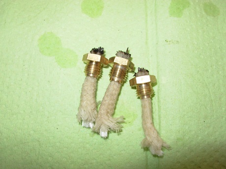
Heute habe ich die Dochthalter gefertigt. Aus Sechskantmessing 10mm wurde zunächst das Gewinde und die Bohrunghergestellt. Anschließend abgestochen und die obere Kontur angedreht.
Weiterhin hat der Brenner noch einen Stützbock erhalten. Er ist mit einer Madenschraube am Brennerrohr befestigt.
And on it goes.
Today I made the wick holders. First, the thread and the hole were made from hexagonal brass 10mm. Then the upper contour was cut off and turned on.
Furthermore the burner got a support. It is attached to the burner tube with a grub screw.
19.01.2019
Heute war der Postbote da und hat mir die Docht als Meterware gebracht.
Die Dochthalter hatte ich für den 4mm Docht mit 4mm aufgebohrt.
Jetzt stellte ich fest, dass diese Bohrung zu groß war, der Docht fiel einfah hindurch. Ich habe mich dann entschieden, den 5mm Docht in die 4mm Bohrung zu bringen. Mit etwas zusammendrücken ging das auch.
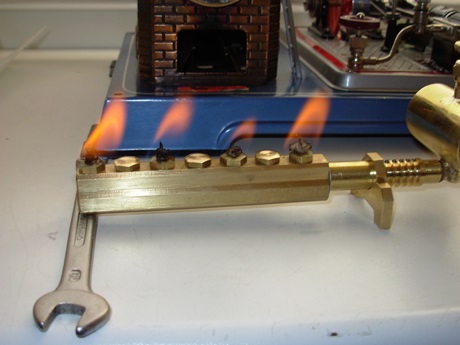
Bei den ersten Versuchen mit dem Spiritusbrenner stellte sich heraus, dass nach ca. 2 Minuten der Kessel ordentlich Dampf machte. Die Dampfentwicklung war so stark, dass der Kessel, trotz Volldampf der Maschine, immer noch über das Sicherheitsventil abblies.
Ich habe mich entschlossen, drei Dochte zu entfernen und den Brenner nur mit 4 Dochten zu betreiben. Jetzt dauerte es gut 3 Minuten bis der Kessel unter Volldampf stand. Die Leistung reicht auch für die volle Dampfabnahme der Maschine.
Today the letter carrier was there and has brought me the wick by the meter.
The wick holder I had drilled for the 4mm wick with 4mm.
Now I found that this hole was too big, the wick fell einfah through. I decided to put the 5mm wick into the 4mm hole. With a little squeezing it worked.
During the first tests with the alcohol burner, it turned out that after about 2 minutes the boiler made a lot of steam. The steam development was so strong that the boiler, despite full steam of the machine, still blew off over the safety valve.
I decided to remove three wicks and run the burner with only 4 wicks. Now it took a good 3 minutes for the boiler to be at full steam. The power is also sufficient for the full steam output of the machine.
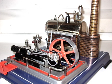
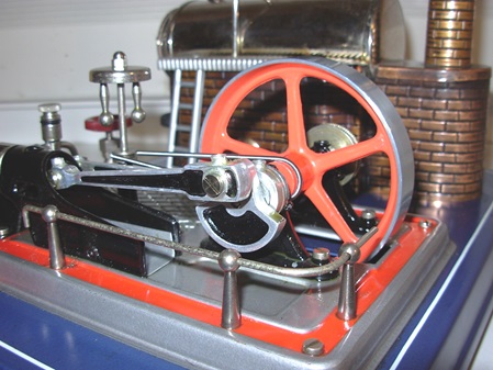
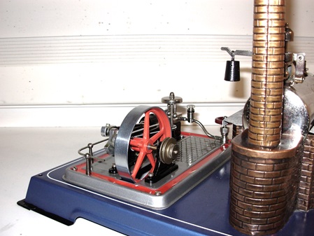
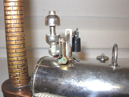
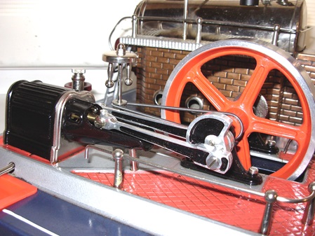
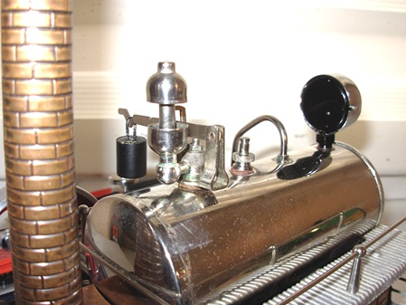
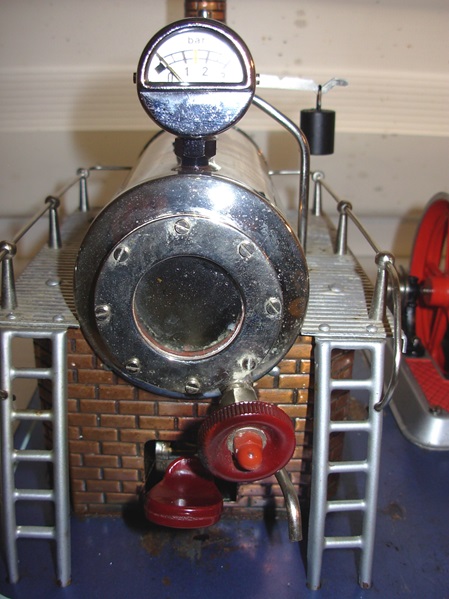
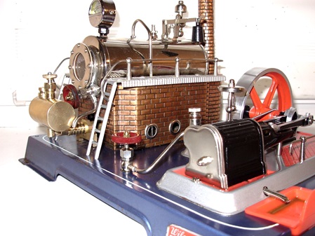
Wilesco D20.
An diese Maschine bin ich günstig gekommen. Nach etwas Putzarbeit und einer Entkalkung des Kessls, schaut sie wieder fast wie neu aus.
Die Zylinderabmessungen sind die gleichen wie bei der D 16. Lediglich die Halterung für den Zylinder ist etwas abweichend gestaltet und das Schwungrad hat einen Durchmesser von 100mm. Die Maschine hat durch den größeren Kessel etwas mehr Leistungsreserve.
This machine I got cheap. After some cleaning and a decalcification of the boiler, it looks almost like new again.
The cylinder dimensions are the same as the D 16, only the holder for the cylinder is slightly different and the flywheel has a diameter of 100mm. The machine has a little more power reserve due to the larger boiler.
08.02.2019
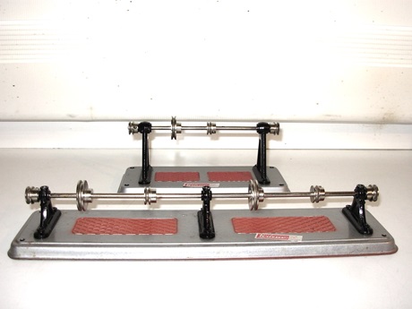
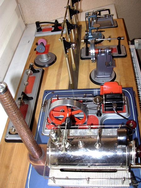
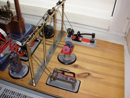
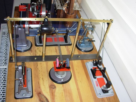
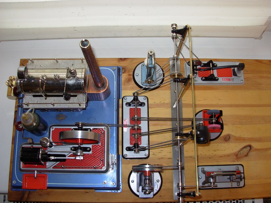
Heute habe ich eine Hochgeständerte Transmission für die Wilesco Dampfanlage gebaut.
Im Anschluss habe ich mal die Antriebsmodelle so aufgestellt, wie ich mir das Vorstelle.
Today, I have built a high-mounted transmission for the Wilesco steam plant.
Subsequently, I have times the drive models set up as I imagine.
10.02.2019
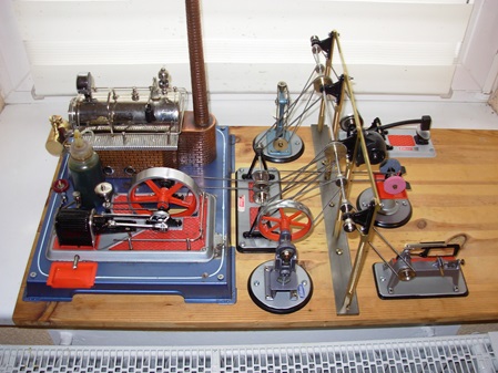
Ich habe mich dazu entschlossen die Anlage anders aufzubauen.
Herzstück der Anlage ist die Wilesco D20 Dampfmaschine mit Spiritusbrenner, die die Vorgelegewellen antreibt.
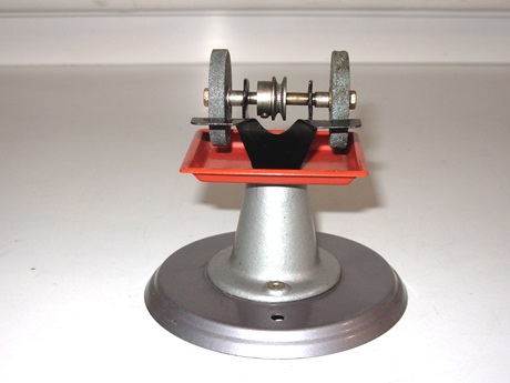
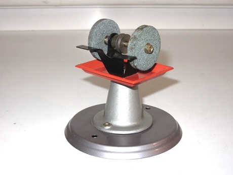
Die Vorgelegewelle versorgt die hohe Transmission über zwei Antriebsriemen und über einen Direktantrieb die Schleifmaschine.
Der Generator wird von der Vorgelegewelle angetrieben oder treibt diese an.
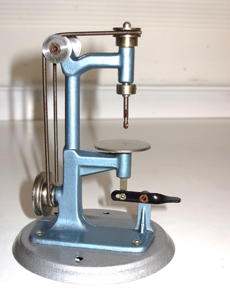
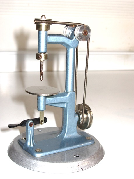
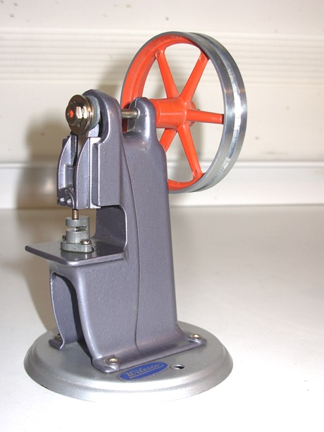
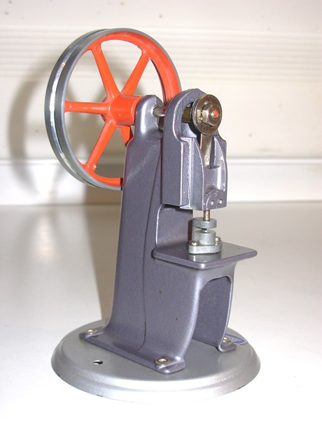
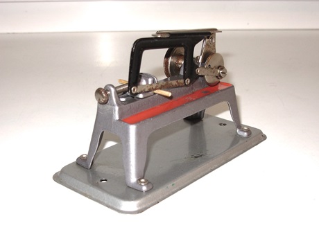
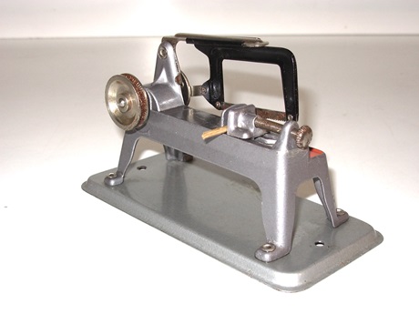
An der hohen Transmission ist die Bohrmaschine und die Exzenterstanze, sowie der Schmiedehammer und die Bügelsäge angeschlossen.
Die hohe Transmission hat nun 4 Stehlager (ergibt weniger Reibung). Die Lagerständer sind 120 mm auseinander. Ferner wurde an einem Ständer der Generator von Wilesco angebaut. Er soll später eine LED-Beleuchtung versorgen und kann gleichzeitig als Hilfsantrieb für die Transmission dienen, wenn einmal ohne Dampf die Anlage gezeigt werden soll.
I have decided to build the layout differently.
The heart of the layout is the Wilesco D20 steam engine with alcohol burner, which drives the countershafts.
The countershaft supplies the high transmission via two drive belts and via a direct drive the grinder.
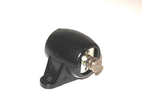
The generator is driven by or drives the countershaft.
The drilling machine and the eccentric punch are connected to the high transmission, as well as the forging hammer and the hacksaw.
The high transmission now has 4 pillow block bearings (results in less friction). The bearing pedestals are 120 mm apart. Furthermore, the generator from Wilesco was attached to one stand. It will later supply LED lighting and can also serve as an auxiliary drive for the transmission if the layout is to be shown without steam.
16.02.2019
Die Stehlager der Transmission haben heute Ölbecher bekommen.
21.02.2019
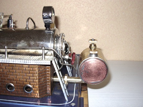
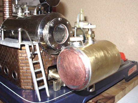
Großer Spiritus-Tank mit Brenner für Wilesco D20.
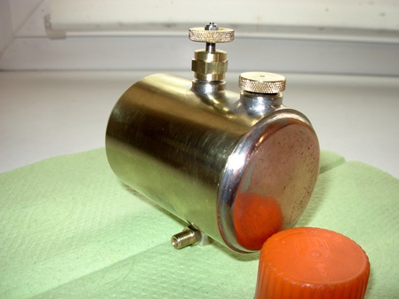
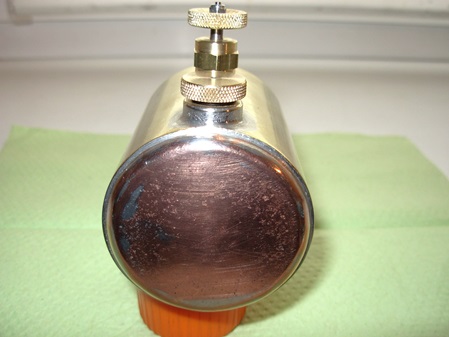
Den kleine Tank am Alkoholbrenner mußte ich 3-4 mal nachfüllen bis das Wasser im Kessel der D20 verdampft war. Der Inhalt war nur ca. 25 cm³. Das war für die D16 völlig ausreichend. Für die D20 allerdings nicht.
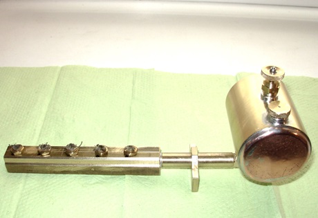
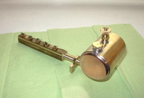
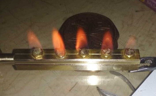
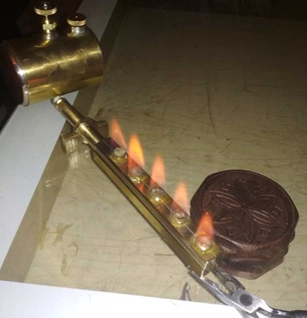
Ich habe dann einen größeren Vorratsbehälter angefertigt und auch einen neuen Brenner. Der Inhalt beträgt nun ca. 120 cm³ und der Brenner hat nun 5 Dochte mit 4mm Durchmesser. Die Dochthalter wurden mit 3,5mm durchbohrt.
Der Kessel macht mit diesem Brenner ordentlich Dampf. In ca. 8-10 Minuten ist der kalte Kessel auf Betriebsdruck von 1,5 bar.
Large alcohol tank with burner for Wilesco D20.
I had to refill the small tank on the alcohol burner 3-4 times until the water in the boiler of the D20 evaporated. The content was only about 25 cm³. This was quite sufficient for the D16. For the D20, however, it was not.
I then made a larger reservoir and also a new burner. The content is now about 120 cm³ and the burner now has 5 wicks with 4mm diameter. The wick holders were drilled with 3,5mm.
The boiler makes decent steam with this burner. In about 8-10 minutes, the cold boiler is at operating pressure of 1.5 bar.
